
The Wilderness SST was designed around 1997 by Wayne Burdick, N6KR of Elecraft fame. It was kitted (by Wilderness Radio) and sold well to excellent reviews. On eHam the rig scores 5.0/5 from 33 reviews. It is an exercise in minimalist design, and there is obvious lineage to be seen in how certain aspects of the SST design found their way into the Wilderness range of QRP radios, such as the way the receiver is coupled to the PA output and monitors the transmitted signal, and the audio-derived AGC. It was respected among the QRP crowd in the USA (it appears in a list of QRP kits on Wikipedia, most of which are from US sources) but was not widely known here in VK. Fortunately, all of the resources and more to build this transceiver are easily found online.
The original Wilderness SST article in QRPp, the SST Construction Manual , the archive of 6 years of SST discussions on the QRP-L list, Dave AA7EE’s recent build and detailed narrative, and a build by JH1PJL with modified circuit here are just some of the SST resources to support a scratch-build. Others worth checking out include JE1TRV’s build, JN3DMJ’s build, W0CH’s kit review, a performance review by AA7QU at Adventure Radio, W4HH’s build, WA8YWO’s has two, and a profile in December 2000 QST. There were also European builds (DL3HRT). Here is a pic recently posted by Wayne, taken around 1998, that shows his Wilderness designs: SST, NC40A, Sierra and the first K2. I am not aware of any VK builds, so fill me in if you have one or know of any.
My motivations for building the SST were two-fold. Firstly, I wanted a homebrew CW portable rig for SOTA activations, to give me an additional mode and band over what the OzQRP MST400 provides (40m SSB only). 30m seems like a worthwhile second band for SOTA. Recently, Andrew VK1DA/VK2UH reported that he worked EA5TX on 10.118 CW from Livingstone Hill VK2/SM-09 (932m, 6 points) using 10 watts (IC703). ’30m may well take over from 20m for the long path DX window to EU… it’s worth checking 30m at all times of the day, it adds another dimension to your activations’, he wrote to the SOTA Australia yahoo group.
And secondly, having finally finished the Summit Prowler One (a 40m SSB scratch-built VXO-based transceiver) I wanted to experiment further with simple VXO-based superhet transceivers using computer crystals. SST looked like a good project to get more experience with this genre. That it was a CW transceiver presented an additional challenge, to activate a SOTA summit with nought but a paddle. I have not had a CW QSO since 1980.
Reading through the SST QRP-L archive brought back the heyday of VXO crystal homebrew QRP CW rigs. Most of the mods are discussed repeatedly and involve builders swinging the VXO further, widening the narrow filter, trimming the BFO frequencies, mods for 21MHz, taming the LM386, and reducing sidetone volume.
Circuit
The circuit is a superhet receiver with a 4.194 MHz IF and a 14.318MHz JFET VXO, mixing to 10.124 MHz. The series-L in the VXO circuit pulls the frequency coverage down by a few kHz (for a 15 to 20kHz spread). The mixer and product detector are SA612s. The transmitter mixes the VXO with a second BFO for 10.1 MHz (another SA612). The driver is an LT 1252 video amplifier and the PA an MRF237 or equivalent. T/R switching is via diodes, allowing the receiver to stay powered up and act as a signal monitor, providing sidetone.
PCB
My construction commenced as usual by choosing the case and drawing up a board layout in pencil on a full-sized paper blank. I prefer long and thin boards ; around 11 x 6cm . I have started to mount these vertically to save space. Using double sided board I layed out the receiver and transmit mixer on one side and the driver, PA and LPF on the reverse side. The BD139 was positioned at the bottom edge of the board to allow heatsinking against the chassis. Strategically placed holes drilled thru the board allow +12v and RF drive to be passed through with wire pigtails, minimising jumpers and point to point micro coax.

Next, the crystals were tested using a G3UUR oscillator from the junk box to make sure they oscillated and to document frequencies.

The ten 4.194 MHz crystals oscillated within 140Hz with three landing within 10Hz — these were soldered into the IF filter. The next two closest were soldered into the two BFOs (receive and transmit).

The rest of the build was unremarkable, other than this being the first time I have used SOIC ICs (the only way I could buy the LT1252). The board has a curious mix of DIP and SOIC ICs.

VXO
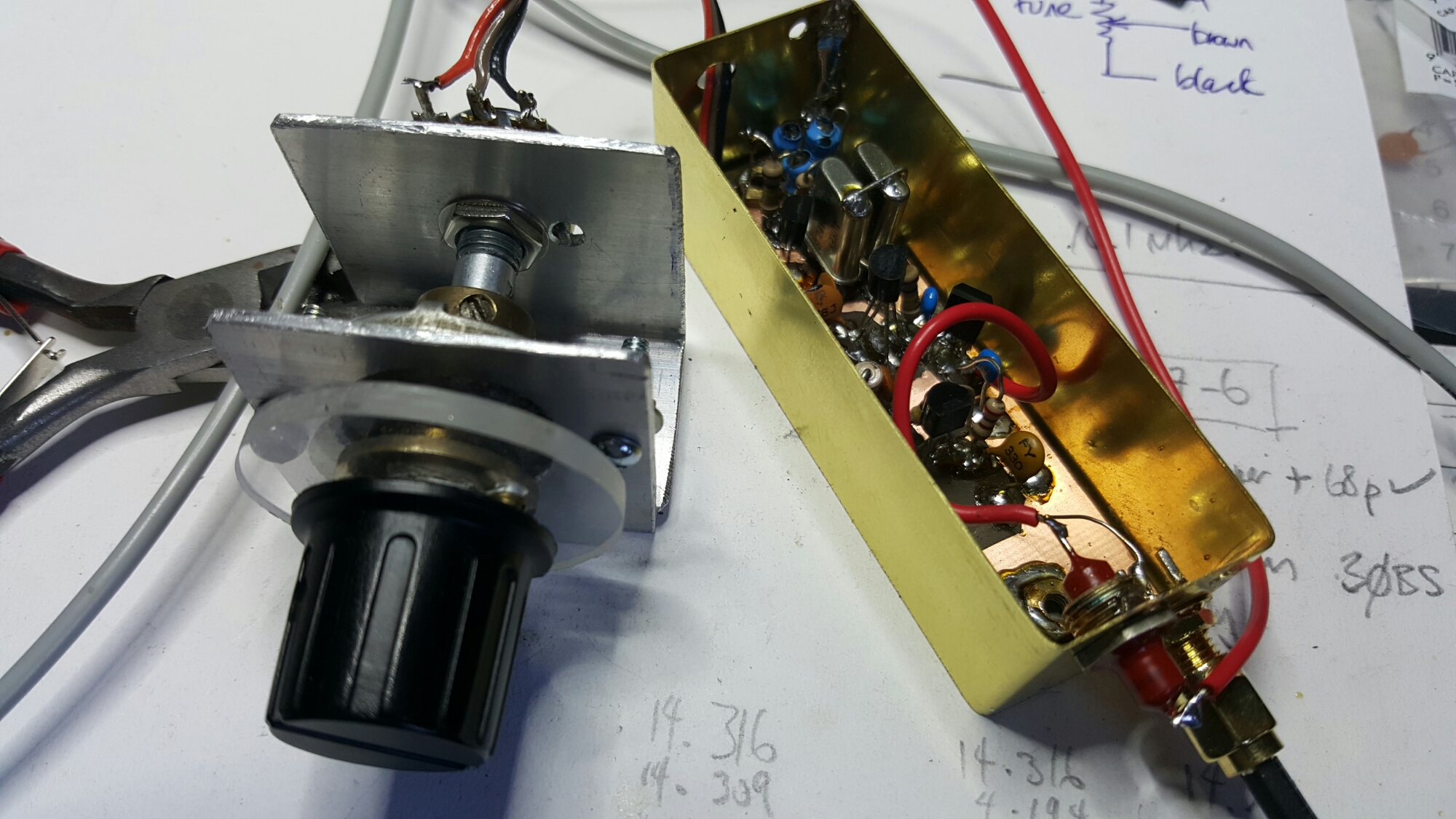
I made a separate board for the 14.318MHz VXO, partly for some physical separation from the transceiver board in ther interests of screening and stability , and also to modularise the rig slightly. The SST VXO uses a J310 FET with MVAM108 varactor tuning and no buffer. After construction, I could not get it to oscillate. I am beginning to wonder if I have a congenital allergy to FET oscillators, because this is the second one I’ve built that would not yield the Joy Of Oscillation (JOO). I think that it may be that FETS (unlike bipolar transistors) have dozens of different pinouts, and that pinouts for the same part number can vary amongst the different manufacturers. My J310s were bought several years ago in an eBay bag of 25 and have no recognisable manufacturer’s branding. I suspect I have the leads wrong. Or I bought a bag of duds. Anyway, sometimes in radio craft, time and one’s level of personal enthusiasm are of the essence, and given that there was no reason to use a FET in my VXO, I pulled it and replaced it with a trusty 2N3904 which gushed JOO on first power-up.
Testing and extending the receiver
On powering up the main board the audio stage hissed quietly but on tuning around the intermediate frequency on the station Icom 746Pro it became obvious that the receiver BFO (4.194 MHz) was not running. The receiver’s BFO uses the second SA612 mixer’s internal oscillator and is comprised only of a pair of capacitors and the crystal. Stumped for a while, I decided to un-solder these parts and rebuilt it with fixed capacitors. With the parts removed I continuity-tested between the SOIC IC’s pins 5 and 6 and their respective tracks. Open circuit on pin 5. These pins are so small it takes magnifiers, lamps, a steady hand and the removal of nearby components to find something as simple as this. With the joint reworked and the parts back in place, Joy (Of Oscillation)!
My first impression of the receiver with a 40 meter dipole attached was how little gain there was. There were a few fleeting weak CW signals to be heard but it was some way from being usable. I concluded that the low signal output was a combination of factors, including a non-resonant antenna, poor propagation, and the fact that it was designed to be a headphones-only proposition. I added a pair of BC549 audio preamp stages between the (balanced) outputs (pins 4 and 5) of the product detector and the LM386. This brought audio levels up such that listening on a speaker on the desk at full volume was (just) acceptable.
But the receiver was still too quiet for my liking. So I added a 2N3904 post filter amp, built Manhattan-style, complete with a very uncharacteristic (for me!) upside-down transistor, jammed between the IF filter and pin 1 of the SA612 product detector. This resulted in a further increase in gain. Touching the base of this transistor generated a buzz, a good sign that the back end of the receiver was working and had sufficient gain. But band noise and the occasional hint of a signal were still unacceptably low — signal coupled from an antenna would drop at the last IF filter crystal. I thought about stripping the filter and checking the crystals, although I already tested each one before soldering them in.
But before that, I decided to build a 30m bandpass filter (kitsandparts.com) and a single 2N3904 post-filter amp stage (of generic design) for the receiver front end (i.e. as an RF amplifier and BPF stage), just as I used in Summit Prowler One.

I reproduced a 30m version in one evening after dinner. The circuit called for T50-6 (yellow) toroids, of which I had none. I did, however, have a little bag of four T37-6 toroids, and the BPF circuit specified all inductances, so I used the excellent toroid calculator on toroids.info to determine the number of turns of 28 gauge wire on a T37-6 for the specified inductance, wound them, and then used my digital LC meter to make final adjustments to the turns to land on the right micro-Henry value. On the little T37 toroids, compressing and expanding the turns makes a big difference to the inductance, much more so than with a T50 core. What a life-saver the digital LC meter is! Special thanks to David VK3KR who not only introduced me to this tool but gave me one several years ago!
The BPF and RF stage made a big difference. Band noise appeared, with the distinctive hollow-pipe sound of a narrow IF filter, and it dropped when the antenna was removed, and… CW! The receiver was now working. Over the next few nights, at or around sunset, and on a non-resonant antenna (40 meter dipole) I heard VK2, ZL3, JA1, S57 and others. As Dave AA7EE has reported, the CW signals pop pleasingly out of the noise as you tune across them, and the filter is clean and sharp, despite using only three crystals.

VXO frequency range
Getting the VXO on frequency presented the usual juggling act. With my last MVAM109 soldered in place and the VXO all snug under its hand-made brass cover (cut and folded from a piece of modeller’s brass stock, Hearns Hobbies) I got 10.089-10.116. A nice 20kHz spread but only half of it inside the band. I was not alone on this result… on 16 Apr 1998 Wayne responded (QRP-L) to an early SST builder who had achieved a useful 20kHz swing using an MVAM108 on 20 meters but had fallen a few kHz below the QRP calling frequency (14.060). Wayne explained that a VXO frequency range can be raised by reducing the minimum capacitance of the varactor (that means replacing the MVAM109) or reducing series L (which also reduces the VXO range). Another suggestion is to add crystals in parallel, while recognising that the further you diverge from a basic Colpitts oscillator the worse its stability will be.
The original SST kit was sold with one each of MVAM108 and MV209 varactors, as they offered different tuning ranges based on minimum and maximum capacitance. My 1SV149 covered almost the same range as the MVAM109 in my VXO. I reduced the series inductance, settling on 4.7, 1.5 and 1uH inductors in series (7.2uH) and settled for a coverage of 10.104 to 10.118MHz. I used a Johnson Bros 6:1 vernier reduction drive to give about 2.5kHz per turn.
The vernier flange supports a clear perspex disc with a printed paper marker piece, backlit by a white LED.

Testing the transmitter
The transmitter worked first time and required no adjustments. The BD139 looks to be delivering about a watt and without a heatsink gets mildly warm after about 5 seconds key-down. The break-in is immediate and you hear when the other station starts sending before you have finished calling him, which happened quite a lot when I tried to respond to DX CQs! The keying appears to be smooth and click-free.
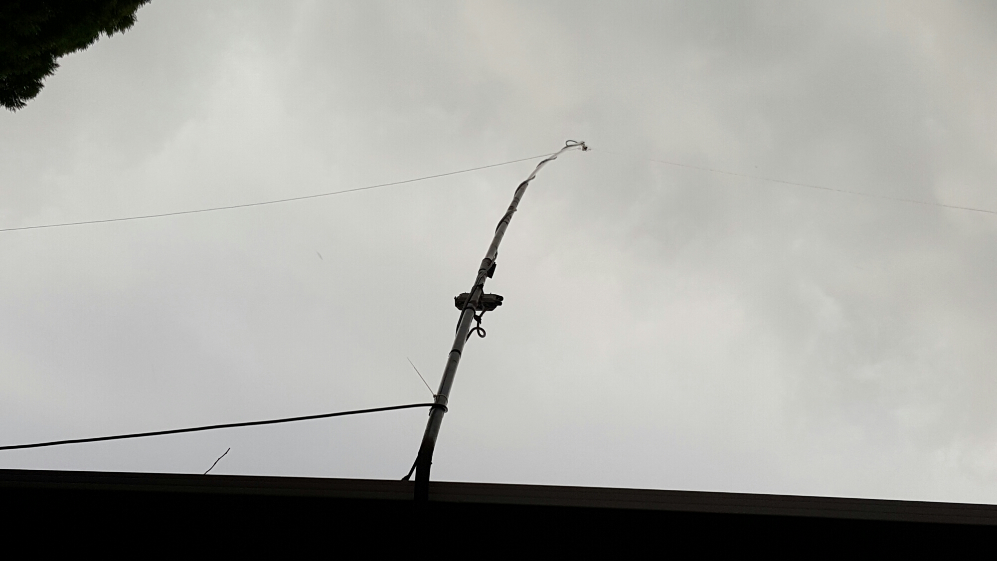
30 meter antenna and first QSO
To make some contacts on a QRP rig from home I needed a resonant 30 meter antenna. I used the house’s ‘hockey-stick’ facia TV antenna mount as the base for a support. I removed the top piece of 20mm aluminium tubing and added a telescoping 16mm 3 meter piece. At the top I strung a 30 meter inverted-vee made with Perspex centre and end insulators made from multi-strand speaker wire, going relatively cheap at the local hardware warehouse, with the ends tied to the gutter braces. The apex must be about 12 meters above the ground. The feed-line is about 20 meters of RG-58, not ideal but on hand and convenient. According to this coax calculator, attenuation at 10MHz is 0.843dB, meaning my 1 watt becomes 824mW at the antenna.
With the transmitter and antenna done, I found myself sitting at the bench listening to all sorts of DX QSOs. I have noticed that DX CW QSOs are mostly mercifully short — station responds to DX CQ, DX station echoes callsign, caller sends ‘5NN 73’, each station dits a few times and it’s all over. I reckoned I could cope with this, despite not pounding the key in anger for over 35 years. I have done a small amount of listening to on-air CW and have found some familiarity with the phrases and exchanges of a QSO. Next thing, out of the blue comes a louder than usual CQ call from VK5LJ, Lawrie in Greenock. I called him with my rusty hand-keying and he responded with 549. First QSO over a distance of 666.03 km! The American QRPers like to work out the miles per milliwatt. I make it 0.43 miles/milliwatt, or 757 yards. Not exactly record-breaking but you have to start somewhere.
Lawrie asked me several questions and I was suddenly in a CW ragchew! My receiving is so rusty and coupled with the excitement I only got about half of what Lawrie sent. We exchanged emails later, and he was very encouraging of a new CW op on the band. I see on the DX clusters that Lawrie is a keen 30m CW man with a string of exotic DX to his name. I sent him a few pictures of the rig, all sprawled around the bench. For the rest of the weekend I spent my key time calling exotic DX but was not heard. Maybe a little pair of boots are what’s needed.
IRF510 amplifier
In the planning stages I had wondered if 1 watt from a BD139 would be practical, given our current place in the cycle. I found three circuits for an IRF510 ‘after-burner’, good for 5 to 10 watts, one on Farhan VU2ESE’s blog, ‘Mini-boots’ by Wayne McFee NB6M on the Norcal site, and the Tuna Topper ][+ at QRP.me built into a tuna tin (of course). The circuits are mostly similar, and I made up an amalgam of the VU2ESE and NB6M designs. I etched a small board to fit over the empty space on the transmitter side of the main SST board, next to the BD139 stage.
The amplifier does T/R switching with an RF-sensing relay so the problem of integrating the extra PA stage with the SST’s T/R switching was avoided. Also, it can be switched in or out of circuit, making a ‘lo/hi power’ switch (1w/5W) a possibility. This preserves the SST as a true QRP 1 watter for when conditions are good or when chasing miles-per-milliwatt kudos, but gives you the higher power for the rest of the time, when you just want the other guy to hear you.
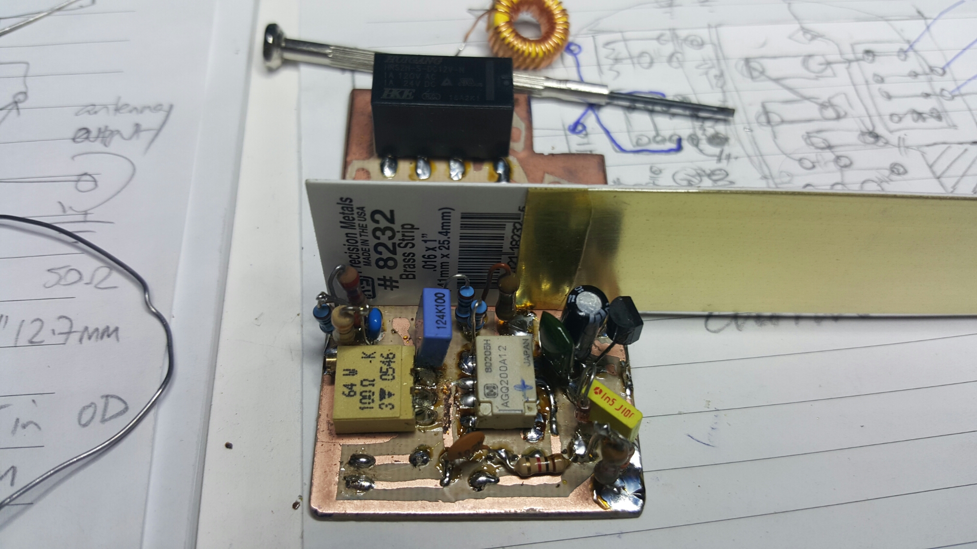
The IRF510 amplifier became a bit of a squeeze on the limited board real estate, but worked fist time and drew a healthy 0.8 amps at 12 volts, which should be more than 5 watts into the antenna. The RF sensing switch which controls the bypass switching works perfectly, with a short hang when the key comes up, but not long enough to compromise the QSK at the speeds I send at.
Keyer and paddle
In a CW QRP rig intended to be used portable you need all the creature comforts you can get. A built-in keyer and a palm-fitting paddle are a must for crouching or standing on a cold field or summit. After a bit of research I decided that the Hamcrafters keyer from Art Hambleton K1EL was a good option. I got the K16 Keyer Kit (externally powered), $US19.95, with shipping $US32.45 or about $AUD44. The kit arrived in under 10 days. It went together easily. Its software is packed with features, most of which I’ll never use. Speed control with a panel mounted potentiometer and 4 memories behind push-buttons is all I need.

For a paddle, I initially looked at the QRP Guys who have several nice keyer and paddle kits, including this one. However the delivery wait from the US to VK got to me and an hour spent with a hacksaw, double sided board and a hot iron, I had a rough homebrew one made up. The settable contact points are brass nuts and bolts. It’s simple but it works.

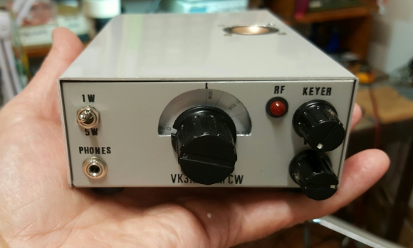
Boxing up
Having chosen a nice compact aluminium case (Rockby) before designing the main board (this way, you know it’s going to fit), boxing up was straightforward.

I gave it the VK3HN ‘Summit Prowler’ treatment, grey panels, black rub-on lettering, and several coats of a matt clear spray paint.
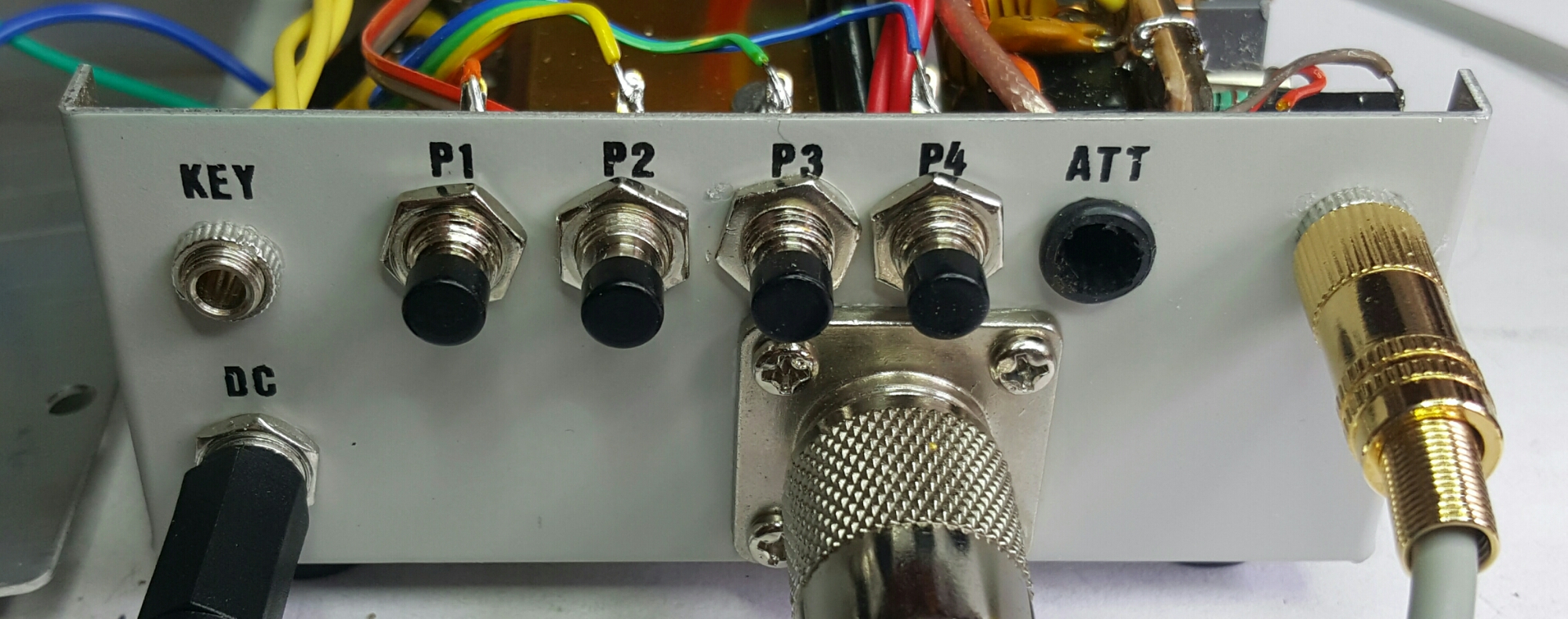
The rear panel has sockets for power, antenna (SO239), key, paddle and the keyer’s push buttons. There is a hole for a switch for an RF attenuator if I decide to add one. The attenuator would substitute for the SST’s RF gain control, which I judge to be unnecessary. RF gain may be important if you live on the US west coast where bands are crowded with kilowatts, but on 30 meters in VK3, a very strong CW signal is likely to be the exception. The front panel has the tuning knob, audio gain, 3.5mm headphone socket, signal LED and keyer speed control.
The dial is a Jackson Brothers 6:1 reduction drive coupled to the one-turn potentiometer which varies the DC across the varactor. I cut a clear perspex disc and a printed paper disc for band markings and mounted these on the reduction drive’s flange. This allows actual frequency readout in the traditional fashion, by reading off the dial. It’s accurate to about a kHz. The dial is back-lit with a tiny high-intensity white LED.
More QSOs
The 5 watt PA helped me to make more QSOs given the current patchy band conditions. On 8/12/2016 I answered Brian VK2EBN’s CQ, and signals held up for about 15m. Brian is in Newcastle and was using an FT897 with 100 watts. That’s 803km or 0.16km/milliwatt. Equivalent distances are London to Hamburg Germany, Odense Denmark or Geneva Switzerland; if I was in New York, to Toronto, Detroit to Charlotte NC. It was my first QSO with the keyer and homebrew paddle. Since then, other QSOs have followed.

| Datetime UTC | Call | RST sent | RST rcvd | Pwr | Comment |
|---|---|---|---|---|---|
| 2016-12-04 11:02 | VK5LJ | 599 | 549 | 1w | First QSO with Lawrie in Greenock South Australia; 666 km; 430 miles/watt. |
| 2016-12-8 10:50 | VK2EBN | 599 | 579 | 5w | Brian in Newcastle, NSW; 803 km; 99 miles/watt. |
| 2016-12-18 11:31 | VK5LJ | 599 | 579 | 5w | 2nd QSO with Lawrie. |
| 2016-12-19 09:25 | VK2AOH | 599 | 339 | 5w | Nick in Bathurst, NSW; 623 km; 77 miles/watt. |
| 2016-12-22 10:35 | VK5EEE | 599 | 559 | 5w | Lou in Adelaide, South Australia; 665km; 82 miles/watt. |
| 2016-12-31 10:35 | VK4RF | 599 | 559 | 5w | Rick in Brisbane; 1319km; 164 miles/watt. |
| 2016-12-31 10:40 | VK2IO/P | 599 | 559 | 5w | Gerard, near Sydney. |
| 2016-12-31 10:45 | VK2IG/P | 599 | 519 | 5w | Mike, Gunardoo, NSW. |
| 2017-01-02 19:15 | ZL1BYZ | 599 | 559 | 5w | Aukland, 1,612 miles, or 322 miles/watt. |
On a summit
I took the SST to Mt Disappointment (SOTA summit VK3/VC-014) on New Years Day 2017 for the SOTA rollover party. About 2 dozen stations were on mountaintops around VK1, 2, 3, 5 and 7. I got four QSOs to activate the summit, and I was pleasantly surprised with the sound and performance of the SST on a mountain, away from the suburban noise at home. As a result of this first CW-only activation, I christened the new rig ‘Summit Prowler Two’. Here’s a video of the highlights:
Wrap up
The SST works very well considering its simplicity. The best features of the rig are its low parts count, excellent QSK and a clean, stable and trouble free transmitter. I like a ‘gainy’ receiver and so I added two additional transistor gain stages. As a comparison, I suspect that my SST probably has a similar amount of pre-product detector gain as Wayne Burdick’s next design, the very popular Norcal Sierra, which uses an MC1350 as an IF amplifier.
The audio preamps bring levels up for a speaker in a quiet shack. I can see why people loved it back in its heyday, 18 years ago. Recommended for anyone looking for a simple CW only monoband superhet transceiver project, without the complexity of single sideband generation, more complex VFOs or band switching.
Notes
Here’s a summary of the mods I built into my SST:
- Trimcaps in the RX and TX oscillators to place the received signal in the center of the passband, and to put the TX signal on the same frequency as the RX signal
- A BD139 for the final instead of a 2N3553 (or MRF237), both of which are fairly much unobtainium without waiting for an order from the USA or offshore eBay supplier. Dave AA7EE suggested a BD139, and the recent discussion of this ubiquitous transistor’s usefulness as a QRP final by Pete N6QW on Soldersmoke#190 was enough to convince me to try it
- A Zobel network (series capacitor and resistor from pin 5 to ground) was added to the output of the LM386 to fix instability (a sharp audio howl) at full volume
- Alternate capacitors in the crystal filter to widen the response, as suggested in the manual (Dave tried 47pF for C6 and C9, and 120pF for C7 and C8, but later reverted to the manual’s values)
- A pair of BC549 transistor AF preamps between the SA612 product detector and the LM386 inputs, to improve the overall gain of the audio stage
- An IF amplifier stage using a 2N3904, installed just in front of the SA612 product detector, for some IF gain
- Replaced the MPN3700 PIN diode with a 1N4007 (also noted in Dave AA7EE’s account)
- Used a 1N5819 Schottky diode instead of the prescribed but unobtainable 1N5817 (the difference, discussed here, is as follows — 1N5817 20 V 450 mV drop at 1A; 1N5818 30 V 550 mV rop at 1A; 1N5819 40 V 600 mV drop at 1A; in practice, the additional voltage drop should be inconsequential)
- Used an available varactor Toshiba 1SV149 from local supplier Minikits instead of the MVAM109 (now unobtainium).

Great job Paul – and good to know that a BD139 does, in fact, do the trick. I particularly like your use of a vernier drive, and the calibrated tuning scale – a nice touch. Thumbs up on the 5W amp. Good call on eliminating the RF attenuation control as well – I have not had cause to use mine yet.
Like you, I was impressed with the performance, considering the low parts count of the basic circuit. The QSK is fantastic – I think the fact that the receiver never completely switches off, due to the sidetone arrangement, helps to create a seamless feel to the TX/RX switching. It sounds very transparent. I am convinced I can hear the band underneath my own sending!
Thanks for describing the process of your build. I hope you get much use from, and have many enjoyable QSO’s with, your Summit Prowler Two.
73,
Dave
AA7EE
LikeLiked by 1 person
Thanks for your comments Dave. The BD139 is a ‘find’ for a 1-2 watt QRP final or an IRF510 driver, as I can buy them over the counter here in VK for a dollar. I first used the Jackson drive in front of the tuning potentiometer probably 25 years ago and is one of my building ‘patterns’. The 5W IRF510 amp significantly increases the chance of making and completing a QSO, particularly under current band conditions.
I must thank you for writing up your SST build in such detail. Seeing that someone else has selected a design, and built it with success, is a big part in deciding to scratch build a rig that is 20 years old and long out of kit and circulation. Your SST build confirmed my decision to build. That’s why blogging is important for homebrewing!
Researching and building an SST might have given me a taste for a multiband improved version. A Norcal Sierra, perhaps? What’s your next build Dave?
73 vk3hn.
LikeLiked by 1 person
A Norcal Sierra is a great idea Paul. It’s very empowering to know that we can build these designs, long after the kits themselves have been discontinued. It’s more fun too.
Glad that the write-up was of help. The fact that my build helped to inspire yours makes the work that went into writing that post completely worthwhile. If, by our building and blogging efforts, we can persuade a few folk to move from the realm of kit-building to scratch-building, we’ve done our bit to spread the joy of home-brew.
There’s nothing on the bench here right now. My building efforts come in fits and starts, and I’m in a down period right now. Shame really, as I have all sorts of parts here, but no inspiration. At least I know that when the inspiration hits, most of the parts are already in stock 🙂
73 for now,
Dave
AA7EE
LikeLike
Good luck Dave. You can’t force these things. 73 for now. 😉
LikeLiked by 1 person
Hello
Great job!
Iv built a Sierra from scratch,using perfboard,a band module connector from China and band module pcbs from FAR Circuits.Its the original version from the 1996 ARRL handbook,without abx.Im presently on 12,17,20.30 and 40.Im afraid theres not much chance of us working at the moment as my antenna is useless-need to do something about it.
Theres a photo of my Sierra on the Yahoo Sierra site where I got your details.Its a great little rig and you can get most of the expensive bits over here from the GQRP shop.
Funny you saying that about fet vfos-I couldnt get the Sierra fet vfo to work,after tearing my hair out ended up using the BITX vfo with 2n3904s which is fine and doesnt drift at all after the initial warmup.
Best 72s
Nigel
G0EBQ
LikeLike
Hi Nigel
Thanks for your comments. I saw the 2 photos of your Sierra, nice job, congrats on using perf board — is that the board with nothing (ie. no copper traces) underneath? Or what we call over here ‘vero-board’, strips of copper conductor that you cut or twist-drill thru to make isolated lands? Either way its a achievement to get it going on 5 bands. And you added an S-meter which is useful.
I am considering making one up with relay band switching and a DDS, with clock 1 programmed to the injection frequency for each band, and clocks 2 and 3 the two BFOs. That would make it rock-solid frequency-wise. When you use perf board or make your own simple PCBs you can do these kinds of things. I think it would make an excellent 5 band SOTA/portable CW only rig. I’d add an IRF510 to get it up to 5 watts, you need it here in VK.
73s and 72s Paul vk3hn.
LikeLike
Hi
No its just plain perfboard.I like that because I find it easier to more or less follow the circuit diagram,I run the earth line underneath and power to pins above (thats the orange wire). Im attaching the original article in case you dont have it.The s meter circuit isnt that great,it tends to zoom off to full scale every now and then for no apparent reason.Iv included the rit circuit but have wired it for switched tx offset of 4.5khz to call up to dx stations,no harm in being optimistic! I used ic sockets,but noticed afterwards that Wayne didnt recommend them as they can cause instability-I seem to have got away with it though.Output is only about a watt,think thats because I used cheap 2N3819s as tx driver,but its working so Im not going to fiddle with it now.Best dx is the midwest USA and Florida. Your idea of a dds vfo seems a good idea,its basically the K2 after all from the filter onwards.I think that the SS30 is basically a single band K1. Good luck with it.As you say Oz is a big country,with not that many people compared to over here!
Best 72s
Nigel G0EBQ
LikeLike
Well done on your Sierra Nigel, you really understand a design when you have scratch built it. Remarkable DX on 1 watt, half way around the world. Thats the benefit of multi band, you can chase the openings. One more question, where did you get your band crystals? They are not computer frequencies.
LikeLike
Hi
That was the problem,my vfo runs 2920 to 3040 so I couldnt use standard crystals.Got some off Ebay and a couple off a silent key sale.Had to pay over 20 quid though for a custom 28.833mhz crtystal for 15 which really hurt!
Like you say I really feel that I know it.The rx was fairly easy except fot the vfo but the tx final took a lot of fiddling around,and peaking the band module is very sharp and its easy to hit the wrong one especially on the higher frequency bands.
Best 72/3s
Nigel
G0EBQ
LikeLike
[…] on my pack showed below 10 degrees C, so I packed up and shuffled down the hill, happy that Summit Prowler Two had let me reach out ‘across the dutch’ to the land of the long white cloud for the […]
LikeLike
Paul,
Thanks for all your hard work documenting the build process of this neat little rig!
I’m familiar with the IRF510 afterburner, as I own a homebrew mini-boots amp with the RF sensing switch and have built a functional class D amp from scratch using the fine “handyman’s guide” documentation available online from Paul Harden, NA5N (Ashar’s circuit was a new one for me, thank you).
You say you ended up using a “hybrid” design from these examples. Would you be willing to further explain the final design as incorporated into your SST? Maybe a hand-drawn schematic?
Thanks in advance and for keeping the QRP homebrew spirit alive!
LikeLike
Hi Chad, sure, I am happy to do that, I know that when I read an account of someone’s build I always look for a circuit diagram. I was aware of re publishing the N6KR SST circuit but considering the entire manual is on the net and also that Dave AA7EE requested and got Wayne’s permission to do so there shouldn’t be a problem. Give me a week or so. Regards Paul vk3hn.
LikeLike
Paul,
It’s the design of your IRF510 circuit and incorporation that I’m curious about.
Thanks!!
LikeLike
[…] to think about, the main one being whether or not you want break-in. Having built and used the Wilderness SST (a CW rig designed from the ground up) I know how good break-in can be for CW operating […]
LikeLike
The links to the original article and the manual are 404 now. Would you be able to post some or all of those files, assuming you saved them? Would be very helpful to newbies…
LikeLike
Hello
The original circuit is on YO3DACs site though it does only give the basic cicuit,but you should be able to fill in the detail from AA7EEs article.
Cheers
Nigel
G0EBQ
LikeLike
[…] I started with a 40m SSB monobander (Summit Prowler I), next a Wilderness SST for 30m CW (Summit Prowler II), followed by a 160m AM/CW transceiver (Summit Prowler III). These rigs reinvigorated my love of […]
LikeLike
[…] on a programmed PIC in an 8 pin DIL IC. I’ve used one of these once before in a homebrew Wilderness SST for 30m. You can buy just the programmed keyer IC to build into your own projects; I ordered 2, one for […]
LikeLike