
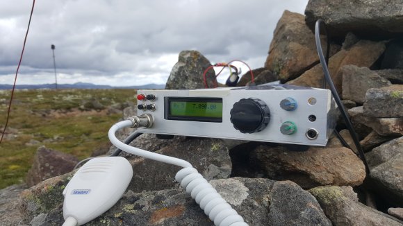
‘Summit Prowler IV’ is a scratch-built six-band SSB and CW transceiver, designed for portable and SOTA activations. It is based on Leon VK2DOB’s MST3 (Minimal Sideband Transceiver, third version) from 2016, with alterations to support multiple bands, my Arduino-based digital VFO/controller and keyer, and a few extras to support portable operating. The transceiver is a conventional single-conversion superhet with 12MHz IF and an si5351 and Arduino Nano-based digital VFO. This project comes after having done more than 50 activations with my 2013 MST Mk I kit radio on 40m SSB. This rig has performed well on 40m SSB (and CW after I added it) and has launched my interest in SOTA activating, turning me into an occasional weekend ‘summit prowler‘.
SOTA is great as it is, and many activators like to pair it with another challenge — working DX from mountain tops, CW only, 23cm or low power. My thing is homebrew. Last year (2016) I started my line of homebrew QRP rigs, affectionately known as ‘summit prowlers’. I started with a 40m SSB monobander (Summit Prowler I), next a Wilderness SST for 30m CW (Summit Prowler II), followed by a 160m AM/CW transceiver (Summit Prowler III). These rigs reinvigorated my love of homebrewing and radio craft, and gave me some great activating moments on southern Australian summits in summer and winter.

Monobanders are fine but with the solar cycle minima approaching I wanted a multi-band rig. From previous experience I know that band switching in a homebrew rig complicates things. The availability of affordable high quality surface mount relays and DC-1GHz RF switches as well as I2C controlled decoders has simplified things, and this build has proved to me that a compact 6 band rig is well within the reach of a moderately equipped homebrewer.
After considerable contemplation, I chose Leon’s MST3 design for the core modules of this transceiver, on the basis of its performance /simplicity trade-off and reproducibility. It is a SA612 receiver but in my experience its performance is more than satisfactory for portable operations. The MST3 supports pluggable band modules (like the Norcal Sierra) so I would have to devise ways of switching these. Of course, this being a scratch-build, I could not resist changing it.
Architecture
The Summit Prowler IV (SP-IV) receiver has a switchable banpass filter, an SA612 Gilbert Cell first mixer, switchable SSB and CW homebrew crystal lattice filters on 12MHz, a second SA612 product detector, NE5534 two stage audio filter, and a TDA2003 audio power amplifier.
The SP-IV transmitter uses a discrete microphone amplifier, discrete diode double balanced modulator, shared IF crystal filter, an SA612 transmit mixer, two stages of pre-amplification (2N3904, BD139) to a single IRF510 and switched Low Pass Filters for 5 watts of RF output. Receiver and transmitter share a T/R-switched and band-switched Band-Pass Filter. Additions include a forward and reverse power meter for measuring and displaying SWR and relative power, an S-meter, and a keyer.
The Arduino controls the si5351, LCD, tuning step and memory select push-buttons, other assorted control lines including key, PTT, mute, band-switching lines based on the current frequency, reading the S and power meter signals, and running the keyer code. It also senses power-down and writes the current VFO attribute set to EEPROM.
Most of the rig reproduces Leon’s MST3 design. See Leon’s manual for full details and circuit diagrams. For the rest of this post I’ll describe my approach, extensions, customisations and results.
RF switching
Being six bands, and with one BPF shared between transmitter and receiver, this rig needed a lot of switches in the signal path. T/R switching the BPFs, switching between the IF filters, and band switching the BPFs and LPFs. My experiments with RF switching continued with this project. I have previously used miniature surface mount Omron relays with success. These relays are of high quality, however they are not cheap and each draws around 30mA when closed.
I sourced some SA630 SPDT RF switches from local disposals outlet Rockby and trialed one switching a 40m antenna between receivers with good results. I used these solid state SPDT switch ICs in the rig whenever possible. In the end I used Omron DPDT relays for switching BPFs, larger DPDT relays for switching LPFs and SA630Ds for everything else.
Band switching
To switch between six sets of bandpass and low-pass filters directly from an Arduino would require 3 digital outputs. To preserve the Arduino Nano’s limited pins for other control functions I used a PCF8574 1-of-8 demultiplexor with I2C. Arduino provides a library for this device, so to use it, simply select an I2C address (grounding its 3 address lines places it at x20) and use the write() method to set or reset each line. I included a 2N7000 on each line as a relay driver, with a LED for a visual indication of the active band.
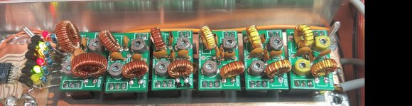
![20180122_075216[1]](https://vk3hn.files.wordpress.com/2017/09/20180122_0752161.jpg?w=580)
Band Pass Filter board.
The main Arduino control script determines which band line to raise based on the current VFO frequency. This mechanism avoids the need for an explicit band switch — you get 10 VFOs, tune each one, and the filters click in when you tune through an amateur band. Outside any of the six frequency ranges all relays are disengaged, creating an effective band edge marker.
Another control line to a second PCF8574 on the LPF board activates the low pass filter for the current band. The LPF relays for the current band are not energised until the transmitter has been keyed (paddle or PTT) to avoid unnecessary battery drain. On the first transmit, the LPF relay pulls in, and remains energised until 1 minute without transmitting has passed. This drops the current drain by 40mA.
Choice of IF
Leon’s MST3 uses a 10MHz IF. I wanted the 30 meter band for CW which meant a different IF. Alternative IF choices, based on low cost crystal availability are 4, 4.195, 5, 8, 9 or 12MHz. I ran up a spreadsheet to check separation between the BFO and signal frequencies and BFO harmonics (more complex mixer products are beyond my simple analysis). A high side VFO, which is better practice for a single conversion superhet, gives the following separation between BFO and signal frequency:
- with an 8MHz IF I get 800kHz between the BFO and 7.2MHz (too close?)
- with a 9MHz IF I get 1MHz between the BFO and 10MHz
- with a 12MHz IF I get 2MHz between the BFO and 10MHz ( good!).
Going lower, 7MHz is out, 6MHz has a third harmonic on 17 meters and is 600kHz away from 60 meters (for the future), 5MHz and 4.9MHz have a 2nd harmonic on or close to 10MHz, 4MHz is only 300kHz away from 3.7MHz.
I chose 12MHz and set about running up two filters with my G3UUR oscillator, eBay counter, Dishal and AADE.
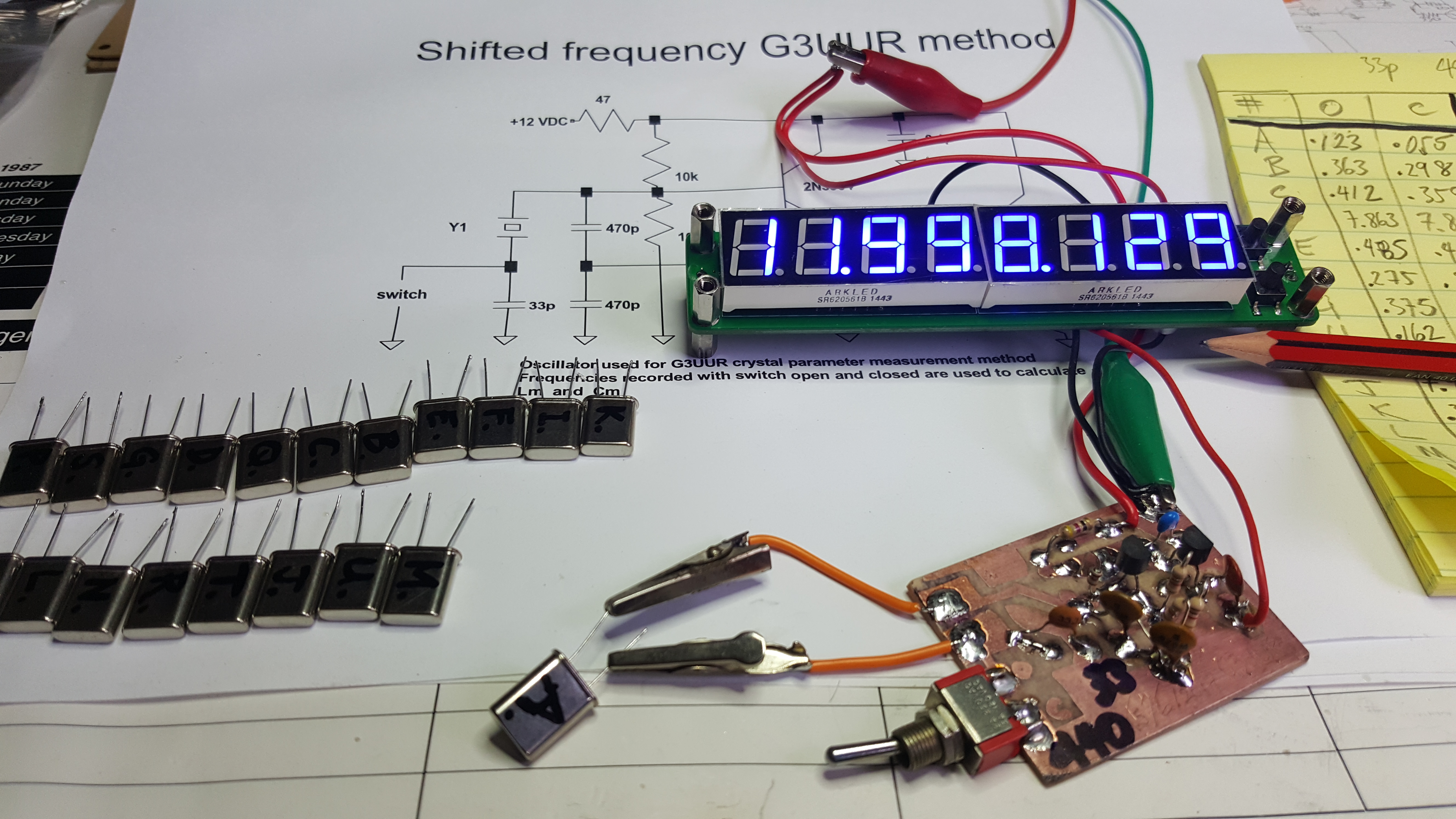
G3UUR crystal testing and frequency measurement.
CW
After two years of SSB use with my trusty MST I added CW using an Arduino keyer and the ‘Arduino generated audio tone injected into the microphone amplifier’ method. It works, but generating a pure keyed carrier is a better approach. In his uBiTx design, Ashar VU2ESE uses the versatility of the si5351 to achieve this. At key down, the Arduino changes the VFO’s frequency from IF +- signal frequency to the signal frequency and unbalances the transmit mixer, so that the rig momentarily looks like an oscillator straight into the PA. Arduino tone is turned on concurrently for sidetone. At key up the si5351 clock reverts to a VFO. A similar approach is used in KD1JV’s SodaPop rig.
I used this method but chose the SI5351’s unused CLK1 to generate the carrier. At key down, the script turns off the VFO clock and primes CLK1 to the current signal frequency, plus or minus the 700Hz CW offset. The keyer code then enables and disables CLK1 to form the CW characters. The CLK1 square wave is directly coupled to the base of the driver transistor via a capacitor. Since the VFO is disabled during CW no signal frequency products are present at the transmit mixer output to interfere with the keyed carrier.
At the same time CLK1 is forming dits and dahs the Tone library is used to put a 700 Hz tone on a digital pin for sidetone, which is attenuated and coupled into the audio amplifier.
Automatic T/R switching is easily done — after 0.8 seconds of paddle inactivity CLK0 (VFO) is reenabled and the rig switches from transmit back into receive.
Controller
The Arduino Nano/si5351/LCD controller follows an established pattern, based on Farhan VU2ESE’s Raduino. It is important to plan out how you will use the Nano’s available digital and analogue inputs/outputs. Using a Nano makes this particularly important as the choice of a directly connected LCD consumes 6 pins. You also need to decide what if any additional I2C devices you will use, and make sure address conflicts are avoided. I decided that this radio would use the VK3HN Arduino keyer (no support for a straight key) and Don Cantrell ND6T’s RF power/SWR monitoring.
Other connected devices include the si5351 (via I2C), BPFs and LPFs mux (via I2C), PTT sense (1 digital pin), T/R switching control lines, and key line (out)(1 digital pin). The option is available for a voltmeter and ammeter (using the INA219) (via I2C). The Nano pin assignments ended up as follows:
- D0 – hardware serial – not used
- D1 – hardware serial – not used
- D2 – rotary encoder up
- D3 – rotary encoder down
- D4 – PTT-sense
- D5 – LCD Register Select
- D6 – LCD Enable/Clock
- D7 – LCD D4
- D8 – LCD D5
- D9 – LCD D6
- D10- LCD D7
- D11- keyer-left
- D12- keyer-right
- D13- (internal LED) – monitors keyer output (flashes CW)
- A0 – Multiplexed buttons– step, vfo-up, vfo-down, filter-select, tune, RF-power-Forward, RF-power-Reverse
- A1 – keyer pushbuttons (3)
- A2 – paddle
- A3 – S-meter
- A4 – SDA
- A5 – SCL
- A6 – RF power (Fwd)
- A7 – RF power (Ref).
Tight, but it all fits. I checked the I2C device’s default I2C addresses — si5351 is on x60, PCF8574 is address programmable (I used x20 for the BPFs and x26 for the LPFs). No conflicts.
I built an Arduino Nano, 16×2 character LCD and Adafruit si5351 on veroboard. I added a PCF8574 1 of 8 (I2C) demux for the band switching lines (6 bands). I cut a new version of a Digital VFO Arduino Nano script I had put together previously. This does the usual rotary encoder reading, si5351 driving via Jason NT7S’s library, LCD interfacing, and I2C using the Wire library.
The script maintains 10 VFOs which are selected by up/down push-buttons and can be set anywhere in the rig’s tuning range (1.8-18MHz). Each VFO remembers frequency, and tuning increment. There is no band, mode or sideband switching — receive and transmit filters and sideband are controlled automatically based on the current frequency. All VFOs and parameters are written to non volatile EEPROM on power down.
Construction
I followed my now well established build approach — a mix of leaded components and surface-mount ICs, hand soldered onto one or two sides of 6″ by 1.5″ boards, hand-drawn and etched ‘muppet-style’. For scratch-building with leaded components, this is my preferred way to work, as I inevitably end up changing or rebuilding certain modules as the rig comes together. The use of 6 x 1.5 inch boards and non-surface mount components makes for a physically bigger rig, but one that is still luggable to a summit.
I designed, built and tested each module separately, some with an Arduino on a breadboard as a test harness. Once debugged, I fitted the module into the chassis and merged the code into the controller script.
Boxing
I made up an aluminium chassis with 50mm angle (3mm front panel and 1.5mm sides and rear panel) on a 3mm sheet base, using pop rivets and M3 nuts and bolts. The front panel presents the LCD and optical encoder (tuning), four control push buttons for frequency step, VFO (band) up/down, sockets for microphone and ‘phones, audio and microphone gains, and switches for an RF attenuator plus a spare. The rear panel hosts DC power and 2 amp fuse, SO239 antenna socket, three keyer memory push buttons, and keyer speed control.
![20180111_083806[1]](https://vk3hn.files.wordpress.com/2017/09/20180111_0838061.jpg?w=580)
Alignment and test
The receiver came up without issue. Having a BFO tune function in the control script made finding the optimal USB and LSB frequencies for my peculiar homebrew crystal IF filter easy. The plug-in BPF modules from OzQrp were easily tested by putting each completed one in series with the VK3HN base station receiver (an IC746PRO) and sweeping the band, tuning to center the passband on the part of the band of interest. I approximated values for 160m, 60m and 30m (bands not offered by the MST3 kits) based on the values in Hans’ QRPLabs band-pass filters. All of the BPFs have acceptable shape and out of band attenuation.
Receiver sensitivity is consistently good from 160-30m, overall receiver gain drops slightly on 20 and 17, however, I don’t have a resonant antenna on these bands which will account for slightly lower received signal levels. To celebrate ‘first signals’ from the basic receiver and VFO al fresco (on the bench) I made this video.
Transmitter testing
The transmitter section also worked without major hitch, although the SA630 RF switch that routes the signal from one side of the BPF bank to the antenna or transmit pre-driver went dead twice, I know not why. These devices are (obviously) not as rugged as relays. It was replaced with a miniature 12v DPDT relay.
On the test bench, I got it transmitting on all 6 bands, into two 100 ohm 5 watt block resistors. Measuring the IRF510 output on a ‘scope, and mapping peak-to-peak voltage to watts using the Hamburg University page, I got about 8 watts on 160 and 80 (very healthy!), 5 watts on 40 and 30, then a drop off to about 2.5 to 3 watts on 20m. Varying the IRF510 bias did not make much difference on 20m.
IRF510s are well known for dropping off above 10MHz. In the article describing a 2xIRF510 40 watt amplifier, WA3EBY graphs this power reduction with frequency. I observed roughly the same rate of decrease as shown on this graph, so I concluded that I was seeing normal IRF510 behaviour. I emailed Leon VK2DOB to get the designer’s thoughts. He agreed that power drops off at 20m but he was able to get 4 watts.
LPF rebuild
I first made up an LPF board with space for 6 filters but as the chassis filled, it began to look a bit over-sized. It used two 9 volt surplus relays per LPF (one on each end), which I decided was unnecessary on a 5 watt PA. So I made a second LPF module to snugly fit the space for it at the rear of the chassis, with a single DPDT relay for each LPF, and 5 LPFs (160, 80, 40, 30, 20+17).
The picture shows the revised LPF board (2-sided) and the assembled module test harness, including a breadboard Nano to drive the I2C PCF8574 demultiplexor. A test script was developed to drive the relays through their paces, including ‘just in time’ relay activation as a power saving measure. Once debugged, the board was mounted and wired into the chassis, and the code added to the main control script.

LPF board.

Testing LPF decoder and switching circuits.
On air
Once the LPFs for 40 and 80 were made and all the monitoring I could do had been done, I put SP-IV on air for some reports. I immediately got reliable reports on 40m CW around the southern states of Australia. After having used my MST400 since 2014 I am familiar with how 5 watts on 40m to a dipole works, and SP-IV performed exactly as expected.
I am most pleased with the gain distribution and sound of this rig’s receiver. If you play the video I hope you will agree that is has nice sounding, clear and punchy audio. I believe this is due to how the crystal filter worked out, and the strong TDA2003 audio stage. I paid no particular attention to optimising the crystal filter.
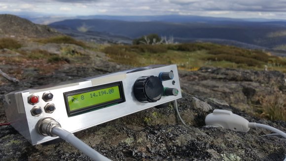
On the summits
Each February Brian VK3BCM hosts SOTA enthusiasts at a ski lodge at Mt Hotham in the Victorian Alps for a weekend of 4 wheel driving and activating. The Mt Hotham ski village it at 1750 meters so you can travel down to a summit from there and still find yourself on a 10 pointer! The timing was prefect this year for christening this new rig on the summits.
I drove up a few days early and camped at nearby Mt Buffalo, so that I could activate four summits before joining the Mt Hotham group. The rig performed to my expectations on the noiseless pristine mountain tops. Clips from three 10 pointers appear in the video above. QSOs were had with ZL, VK1, VK2, VK3, VK4, VK5, VK7 on 20, 30, 40 and 80M CW and SSB. ‘Summit Prowler IV’ was christened in style!

Mt Hotham VK3/VE-006.
Working ZL on 20m SSB, Mt Cope VK3/VG-001
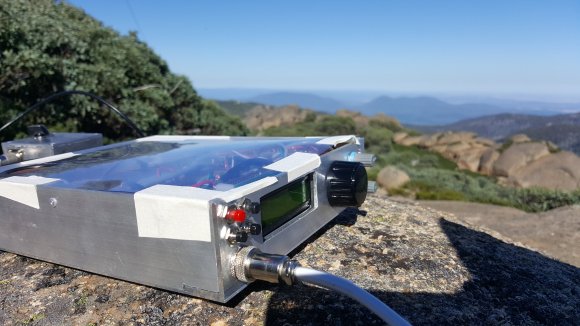
Working 40m CW on The Hump VK3/VE-019, Mt Buffalo.
Mt Cope VK3/VE-005.
Post-build reflection
For a homebrew single conversion superhet rig a consideration for me is the receive mixer and IF/AGC investment. A double balanced diode mixer (such as the ADE-1) makes for a better noise and IMD figure but necessitates a fair amount of AGC-controlled IF gain (up to three stages) and in my experience, can raise gain distribution and AGC alignment challenges. Two SA612 Gilbert cell mixers have sufficient gain to nullify the need for a separate IF stage, and can operate satisfactorily without AGC. In a moderate performance receiver that’s a big simplification.
I got extra ‘loudness’ out of the receiver by using a strong 5 watt TDA2003 audio power amplifier stage and a good quality speaker, properly baffled in the lid of the case. For SOTA in VK, a moderate performance receiver suffices. Weak signal/DX contacts are icing on the activator’s cake, and are really only available under good conditions on 20m. This architecture scores well on the complexity vs performance trade-off.
The transceiver ended up being a bit physically large and heavy for an ideal SOTA SSB/CW rig. For SOTA, I don’t need 6 bands — 80, 40 and 20 would be ample. I also chose some ‘shack sloth’ conveniences like the (heavy) optical encoder and a good quality speaker which, although small, is heavy for its size. For a bit of cheeky fun, here’s a comparison on size and weight with the venerable FT-817:
| FT817 | SummitProwler-IV | |
|---|---|---|
| Width (cm) | 135 | 185 |
| Depth (cm) | 165 | 205 |
| Height(cm) | 38 | 50 |
| Volume (cu. m) | 0.00084645 | 0.00189625 |
| Weight | 1.17kg with battery, antenna, without mic | 1.1 kg without battery or mic |
| DC Power | Rx: 450mA Tx:2A | Rx: 290mA Tx 1.2A |
| RF Power | 5W 160-70cm | 5W 160-17m |
So I’ve ended up with a general purpose 6-band SSB/CW rig which will be fine for portable or some SOTA use. I might hesitate lugging it up a hard summit or long mountain walk. The kit rigs specifically designed for SOTA do not compromise size or weight — they are much smaller, with smaller (cheaper) encoders, no speaker, basic controls including a minimal display, and surface mount componentry throughout. I am approaching the practical limit of wired component scratch building, for me at least.
This was my first attempt to build a multi-band superhet transceiver since the 1980s. Although the band switching and sharing the BPFs between receive and transmit complicate the build, it worked without issue. The rig is stable and reliable on both receive and transmit, across all bands.
Multi-banding a homebrew transceiver is made significantly easier these days by being able to generate any frequency (1-160MHz) via a single line of Arduino code with the si5351 or similar. In the past, generating or heterodyning the VFO at the right injection frequency was challenging to say the least.
That said, each additional band adds space and construction hours to the project. Perhaps a good place to gain experience with a multiband rig would be a two-band rig. Such a project would pose interesting band switching challenges, and give you the operating benefits of two bands, but limit your risk of RTI (Repetitive Toroid-winding Injury), as well as the gumption-trap of the never-ending homebrew rig (see See 12.2 in EMRFD — The ‘Unfinished 7-MHz CW Transceiver’… this radio never seems to be done, being always in a state of modification, justifying the name).
For example, Pete N6QW is currently reworking the K1BQT monobander (Hamradio 1985) but as a two-bander, conveniently using SPDT relays to do the band switching.
Next time
After completing a project like this its always worthwhile to jot down what you would do differently next time. If I build another rig like this, I will:
- Choose symmetrical BPFs with 50 ohm unbalanced (rather than different unbalanced and balanced inputs and outputs) to simplify switching, and I will handle the impedance transformations around the mixers with FT-37-43 broadband toroidal transformers
- Consider diode switching for BPFs as a middle ground between cost, complexity and current draw
- Where relays must be used, I will try out latching relays for BPF and LPF switching
- Try to keep to a receive current budget
- Consider the Motorola RF power FETs rather than IRF510s for more even output on the higher bands
- Try to make it even smaller by employing more tightly packed physical design (without necessarily going to surface mount components)
- Use an LCD that is replaceable (not a surplus one with odd physical dimensions).
What’s next?
I’ve been thinking about a smaller Summit Prowler — with 3 bands, 80, 40 and 20, SSB and CW, an ADE-1 receive mixer, two or three MOSFET IF stages and a simple AGC circuit, SA612 product detector and transmit mixers, 1496 balanced modulator, low height LCD on an 40mm (not 50mm) angle chassis. It will use the exact same script so the rings will share controls and features. With a bit more care in the design of the boards, I reckon I can make one about three quarters the size, whilst still using predominantly homebrew boards and a mix of SMD and thru-hole components, and without losing my eye-sight or my sanity!
In the not too distant future, the LCD, Arduino Nanos and si5351s will be torn out of these rigs and replaced with better options, a Teensy perhaps, with a decent sized OLED, and si570s or the recently announced si549. A new improved MCU/display/VFO unit is a project in itself. I eagerly anticipate the emergence of a suitable combination of components from those who do the homebrew digital work.
Acknowledgements
Thanks to Leon VK2DOB for designing the MST3 and for making it such a reliable design, and for answering my email questions, David VK3KR for bouncing ideas about parts and building back and forth on WhatsApp during the build period., and the VK And ZL SOTA crowd who are prepared to chase a small signal on a noisy band, thereby creating incentive for a project like this.

Federation Range VK3/VN-029, 1490m, 23 Jul 2018.

[…] 6th March 2018: Have built four or five Arduino Nano/si5351 VFO/Controllers now. A post describing my latest Nano/si5351 controlled QRP rig is here. […]
LikeLike
[…] script. Here’s a picture of his rig, a 5-band CW QRP transceiver, quite similar to my SummitProwler IV project. Love your work […]
LikeLike
[…] script. Here’s a picture of his rig, a 5-band CW QRP transceiver, quite similar to my SummitProwler IV project. Love your work […]
LikeLike
[…] year I entered the RD Contest in the QRP category, using my multi-band QRP SSB and CW rig (Summit Prowler IV) as a 5 watt SSB and CW base station, with 80 and 40 meter dipoles. Conditions were rough on […]
LikeLike
[…] sensitivity or other essential receiver characteristics, but in A/B tests with my Icom IC746Pro and Summit Prowler IV (another homebrew project, a superhet 6 band SSB/CW transceiver using SA612 mixers) it is equally […]
LikeLike
[…] completing a 6-band SSB/CW QRP transceiver (Summit Prowler IV) I found myself thinking about a more compact QRP SSB/CW rig for SOTA, with just 2 of the main […]
LikeLike