
The remarkable compact transceivers of Peter DK7IH inspired me to dream up a compact transceiver of my own. This project would be an experiment on a shirt-pocket scale — not as dense as some of Peter’s rigs, but small on my scale. Starting with the PLL VFO/controller along the familiar lines of Raduino (Arduino Nano and si5351), I sketched out a physical design, and it became clear that the display choice would dictate the size of this module. Where small displays are concerned, there’s only one option … OLED.
I bought my first OLED over a year ago, but a dodgy 5v regulator forced out my tiny Adafruit display’s internal magic smoke. I cursed them and swore never to let them into my shack again. Being an unapologetic aesthete, I had other issues with OLEDs. I didn’t like the look of them on some homebrew rigs, where they sit on the panels of big boxes looking like a postage stamp. They work, but look all wrong, like a family room with a bathroom-sized window. Another problem was the large amount of memory required by the display buffer.
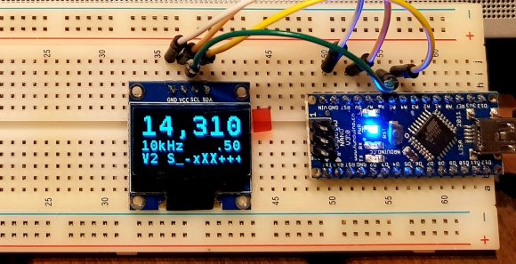
Despite these issues, I decided to make up with these tiny panels, buying a 128×64 OLED with SSD1306 driver. I bread-boarded it with a Nano, ran I2C_scanner to find its address (0x3C) and downloaded an Adafruit driver script. Voila! Worked first time.
Size matters
But the memory problem reappeared. The Adafruit SSD1306 library does graphics which filled my Nano’s memory all the way to the ‘Low memory’ warning. No room for anything else. My ‘SummitProwler’ VFO/Controller/Keyer script already takes up 84% of program storage space and 66% of dynamic memory. So these two were never going to work together.

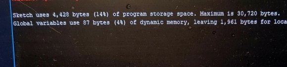
The Adafruit library alone fills up the Nano’s dynamic memory.
A quick search found a discussion thread in the Arduino forum on the prohibitive size of the Adafruit OLED library. The wisdom of the crowd came through again, and a few clicks later, I’d installed the smallest ASCII-only SSD1306 library known to mankind, SSD1306Ascii, by Bill Greiman. Look at the difference… program space reduced by a third, and global variable space reduced from 80% to 4%!
To make the frequency digits as large as possible on the minuscule panel, I selected a large font and used the library’s x2 function. The result looked to be usable on a compact rig.
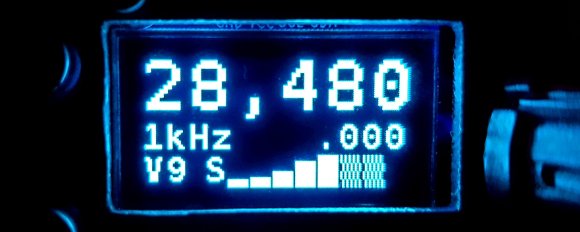
S-meter
The only drawback of this library is that it includes only printable ASCII characters, so drawing the S-meter necessitated a bit of font hacking. There are GLCD font editors that generate code from a drawing of your custom character in an X by Y grid. I grabbed one and designed a font of six 10×15 pixel characters — S1, S3, S5, S7, S9, +x dB. The resultant code didn’t render properly, so I got into a hacking mindset, cycling through a tight trial-and-error loop, adjusting various hex digits in the font character array, and observing the result. After about an hour of fairly mindless trial-and-error, I’d sussed out a set of usable characters. The font is available here.
Adding OLED to SummitProwler VFO/Controller script
All the VFO/Controllers in my homebrew radios use the same script, available here. Each time I use it in a new receiver or transceiver project, I isolate the project-specific code with a #define‘d project label and #ifdef #endif pairs. This ensures only the code required for that project is included in the compiler scope. This is mostly around the UpdateDisplay() method, BFO initialisation, encoder and push-buttons. Most of the VFO, T/R, rig control, metering and keyer code is common. Some code (e.g. PCF8574 drivers for band switching) is small and is left in, even if not used.
After pasting in the SSD1306 code, and wrapping with pre-processor directives, the script settled at 93% program space and 73% global variable space. Code space on the edge of the warning, so there might be some refactoring to be done soon, as I seem to keep adding features!
Physical build
The rest of the build followed my well-trodden path, reproducing the circuit of VU2ESE’s Raduino with an Arduino Nano, Adafruit si5351 breakout, and a 5v 7805 regulator, with the mechanical rotary encoder and push-buttons for VFO selection on flying leads. The two push-buttons on the left allow selection up and down from the 10 VFOs. The frequency step is changed by pushing in the main tuning knob. The other front panel controls are analogue transceiver controls. The two sockets are for an external speaker and PTT microphone. Other essential controls and sockets including DC power, antenna, paddle and 3 keyer memory push-buttons will be relegated to a rear panel.

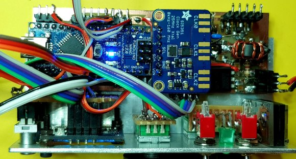

The only departure from the standard Raduino pattern was to add a 100uH inductor in series with the 5V line to the OLED module with bypass capacitors to keep OLED digital noise off the 5V line, from where Peter DK7IH reports it getting into the receiver.
The module is worked out in a custom hand made PCB, mounted behind a front panel cut from aluminum angle.

The si5351’s middle clock (CLK#1) is set to the signal frequency (with a 700Hz offset applied) and keyed in software for sending CW. The 2MA square wave clock is buffered with a discrete MMBT2222 buffer/gain stage, to condition it for injection into a transmitter’s driver stage.
Both si5351 clocks run at the 2MA setting, delivering around 5dBm as measured. In the scope screen below (for the 7MHz band) the si5351 CLK#0 (VFO) is the yellow trace, CLK#2 (BFO) is purple. The VFO is about 1Vpp which is 4dBm. The VFO amplitude drops to 700mVpp on 14MHz, 500mVpp on 28MHz and 300mV on 50MHz. Remember that the actual VFO is running 12MHz above these bands. The BFO runs at about 5dBm.
The CW carrier oscillator buffer (CLK#1) was measured at 12dB gain, delivering 25mW, more than enough carrier to drive a future transceiver’s driver/PA board. On a 12v supply the entire VFO/Controller module draws 80mA, a bit less than one with an LCD would draw.

Wrap-up
The VFO/Controller module is now complete, tested, and ready to drop into a compact case as the heart of a compact SSB/CW transceiver. Write-up of that project to follow as it progresses. If you like this kind of thing, I urge you to check out Peter DK7IH’s blog for an eyeful of amazing compact homebrew achievements.

I’m also trying to build a compact 20 meter SSB transceiver (14.5 CM x 15 CM x 6 CM) based on Peter’s ideas. I’m using the Si5351, but instead of going with Adafruit’s module, I purchased ten of the Si5351 chips from Mouser at less than $1 each, and soldered one onto a little SMT breakout board I got from ebay. Likewise instead of using an Arduino, I got a 32 pin SMT breakbout board and soldered an ATmega328P onto it. The breakout boards were mounted onto a pad per hole perfboard. I’m using the Si5351mcu arduino library which borrows from Peter’s code and the Raduino. The display I’m using is a 32×128 OLED, and I’m using the Adafruit library. So far I’m using about 55% of the flash space. As per Peter’s idea the VFO and BFO outputs are swapped in software going from RX to TX, the product detector becomes the TX mixer. Separate parts are used for the RX mixer and Bal modulator, also separate outputs from the Si5351. I used separate 3.3 v regulators for the CPU-OLED, and Si5351, and feed the OLED via a 100uh choke. I’m running the CPU on 3.3 volts so I don’t need level converters on the I2C.
LikeLike
Thanks for your comment, your project sounds great, using ‘nude’ si5351s and ATMega MCU. DK7IH has inspired a number of projects lately, yours, mine, Glenn VK3PE has also built a Micro 40 style rig in recent days. It could almost be called a trend!
My front panel Nano/si5351 module, the subject of this post, will be used in a bidirectional SA612 transceiver, hopefully more than one band, to be built and tested out this VK summer. I hope to achieve it in a case 95mm wide, 32mm high, about 160mm deep.
Choosing to make a rig ‘compact’ adds an interesting constraint. I’m getting better at cramming it all in, while managing to maintain earthing, screening and getting the layout right.
LikeLike
Hi Paul, looks really great. A nice start for a tiny transceiver! 73 de Peter
LikeLiked by 1 person
Thanks Peter for the inspiration, and your detailed and easily reproduced circuits. Your blog posts are a pleasure to read. Keep melting solder. Old school is cool!
LikeLike
[…] 2018: And another Arduino/si5351 compact VFO/BFO/Controller and CW Keyer, first stage of a compact multiband SSB/CW transceiver. […]
LikeLike
Looking good, Paul. I haven’t had much luck in a brief look at why the Tx side of mine is low level. Been hit with a nasty bug and playing radio is last on the list for now.
Glenn
vk3pe
LikeLiked by 1 person
Get well, Glenn.
LikeLike
Hi Paul – first, I’d like to congratulate you for your projects, which like the ones of Peter DK7IH are a real inspiration for many QRP-loving Hams like me! For one of my next projects I’m trying to upload your VFO sketch on an Arduino Nano, but I get a strange error message: ” no matching function for call to ‘Si5351::set_correction(int)’ “. I think I am using the correct library (the one you have suggested). Any idea what the problem can be? Thank you.
Best 73s de Robert HB9TSE
LikeLike
Hi Robert, thankyou for your very nice comments, my projects are nowhere near as perfectly executed as those of DK7IH so it is flattering to be compared with Peter. Our interests and choice of rigs are obviously very similar.
A quick response, Jason’s library changed, use thus line and it will compile:
si5351.set_correction(cal_factor, SI5351_PLL_INPUT_XO);
Let me know if you have other compile or runtime issues. The wiki pages on the Github repository are written to help people try the script.
https://github.com/prt459/Arduino_si5351_VFO_Controller_Keyer/wiki
Are you thinking of using an OLED or LCD? And what are the origins of that fine looking 80m SSB rig of yours on QRZ.com?
73 72 from Melbourne Paul VK3HN.
LikeLike
Hi Paul and thanks for your super fast response! For my last project (80m SSB RTX) I’ve used the CDV VFO made by your friend Leon VK2DOB – fantastic little thing! The SSB board is my own design, as is the 8-Watt PA. I’ve developed the SMD boards on the (chinese) Easy-EDA website: easy, cheap and fast. If you send me your email address at my callsign@bluewin.ch I will send you some pictures so you can see what’s inside. Now for the first time I’m starting to try to program my own Si-5351 based-VFO and I’m struggling a bit, as you can see… Now I get the following error: ” ‘cal_factor’ was not declared in this scope” which I suppose makes sense as it was not declared in the first place… Maybe I’m not using the latest version of your sketch?…
73s from the French-speaking part of Switzerland
Robert HB9TSE
LikeLike
Robert,
For now replace cal_factor with 1000. Email me using my email on qrz.com for easier collaboration.
— PT.
LikeLike
Code not working..
typedef struct VFOset_type VFOset_type
LikeLike
Code not working
typedef struct VFOset_type VFOset_type
LikeLiked by 1 person
Hi VU3WUR, The Arduino IDE sometimes has problems with structs, it’s to do with how the compiler generates method prototypes. Make sure you are on the latest Arduino IDE. I am on 1.8.12 with no problems.
LikeLike
hi, im running latest arduino ide 1.8.13…any other solution for this
LikeLike
Hi, Im using arduino IDE 1.8.13…then also shows same problem,,sir is there any other solution for this…
LikeLike
Please raise a bug on the Github repository. Then the history will be kept with the code and we will only need to document the resolution once.
LikeLike
ok …done
LikeLike
Thanks, lets resume over on github.
LikeLike
[…] buffer amp on the CW carrier. This unit measures 95x32x45mm and gets its own video and write-up here.Adding support for an OLED display into my SummitProwler script involved a fair amount of code […]
LikeLike
Hi Paul,
I’m in the final stages of my project based on your sketch and everything worked fine until I had the bad idea to upgrade the IDE. I also updated a few libraries (but I don’t think that this could be the issue) and suddenly I’ve got this error message when I want to upload the sketch: ” ‘s_meter10x15’ was not declared in this scope”. Result: the S-meter and the P-meter no longer work as I had to comment the lines causing the error. Switching back to the 1.8.12 IDE version did not change the problem which appears even on your original sketch… Any idea where this could come from (apologies if this is a silly question, but I’m still a neophyte in Arduino programming…)? Thank you. Best 73s de Robert HB9TSE
LikeLike
Hi Robert,
Apols for the late response. I am always cautious when it comes to IDE or individual library upgrades as any deprectation of compiler features or changes to library method signatures can break the code and require some effort in re-testing. A more professional approach would be to have a continuous integration environment in which the code is paired with unit test harnesses and the whole thing compiled and built frequently, automatically. Then, bugs are found and can be isolated immediately. But this is an amateur, hobbyist, best efforts endeavour.
I am on IDE 1.8.12 by the way, so I may experience your issue when I do eventually upgrade.
Did you upgrade your OLED libraries? That would overwrite the mod you made to include the new custom S_meter font. That’s all I can suggest, go back through the install sequence, make sure the library’s fonts.h correctly includes the s-meter font .h file. You say you upgraded a few libraries’, this is likely to be the problem, not the IDE upgrade.
The instructions for adding the s-meter-font.h file can be found on the Wiki tab in the Github repo.
Let me know what you find as I suspect this issue is just around the corner for me as well!
73 Paul VK3HN.
LikeLike
Dear Paul – you are exactly spot on. I initially struggled because in the updated OLED library the “SSD1306Ascii_fonts.h” no longer exists… but I managed to include the custom S-meter fonf in another file and it worked! Lots of trial and error, but eventually that how we learn, right?
While I’m here I would like to ask you something regarding the scaling of the Power-meter, In the code there is a line where you can do this (numbers between 0 and 1024) but I still don’t get it (although I managed to make it work for the S-meter). The voltage I get from the PA is between 0 and roughly 8V (for 8 Watts). However I’ve tried lots of combinations without success (either the P shows only one tick and doesn’t move or it goes full scale on TX, with no in-between). Shall I limit the voltage to max. 5V? Thanks again for your help.
Best 73s de Robert HB9TSE
LikeLike
Hi Robert
Well done for digging in and finding the problem. Note to self, upgrading libraries is probably more likely to break the build than upgrading the IDE. I am not sure how yo get around the overwriting problem, other than manually doing this check.
On mapping for the power meter, the first thing is that I would definitely not put more than 5v on an Arduino digital pin. It appears that 5.4v is the maximum recommended. If you hit it with 8 volts you may well zap it. Use a pair of series resistors in a series voltage divider, sya 1k each, that will give you 0..4v from your 8v sense line.
As for the code mapping, this is the line that matters:
1058 byte s = map(pwr_val, 0, 550, 1, 8);
Have a look at Arduino map() function and you will see what it does, it is a very useful function. In the example above, it maps the value of pwr_val which is expected to be in the range 0..550 (about 2.5v on the digital input) to the corresponding value in the range 1..8 inclusive. Experiment and adjust for your particular project. I take it you are using Serial.println() to trace values to the console. Without that, you are working in the dark!
Your rig must be nearly complete now.
Best wishes, Paul VK3HN.
LikeLike
Plans change. Still working on the little rig, now dubbed the ‘nanoBITx’. I’m going to use the same topology as the ubitx, but only 4 bands. DPDT relays will select one of two LPFs, which will cover 40/30 and 20/17 (or maybe 20/17/15) meters. Final will be 5w a-la DK7IH. First mixer will be MCL, 45mhz IF with surplus cell phone filter and MCL ERA amplifiers. 2nd mix and product detector / bal mod will be SA602/612. 2nd IF is 10.7mhz using old CB filter. RX IF amp (not used on TX) will be MC1350. LM358s for AF preamp/cw af filter, and AGC, LM386 af output. Mike preamp will be inside of 3D printed hand mike with either an electret or carbon mike element, later from an old telephone handset. On CW the MCL mixer is unbalanced via a bias voltage and VFO runs at air frequency. Except for RX IF amp, all stages are bilateral. RX/TX switching around 2nd IF filter uses 74HC4053 fet switches. Will try to squeeze simple CW keyer into the firmware, also will switch to ASCII only OLED driver and borrow your fonts. OLED is 32×128 ‘half size’ display. AGC circuit is from ’95 ARRL HB.
LikeLike
All good. That selection of components sounds good. I’m still hoping to experiment with a homebrew uBitx some day, I want to try the dual conversion, up-converting architecture for myself. Let me know how it goes. The 4053 IF switching is a good option. SA630 is another option but you have to work with the fact that they present 50 ohms, not open circuit, to the unused port.
73 Paul VK3HN.
LikeLike
The half size (32×128) display doesn’t chew up quite as much ram memory as the full sized 64×128 display, maybe that’s why I didn’t notice a problem so far. I’ll keep the option of the ascii driver just in case, but for now the Adafruit graphic driver still ‘fits’.
Granted that the half sized display limits what you can show, but I can still fit 4 lines of text, or two lines of txt plus a double sized font frequency display.
LikeLike
You really don’t need much display data, and if you don’t mind dropping the labels, you can fit a lot of information into 32 characters. I’ve got a rig that uses an 0802 LCD, and I don’t think it us missing anything essential. Readability on the small OLEDs is another issue…
LikeLike
Hello Paul! I would like to switch to a 1.3-inch oled display SH1106. What should I do because the memory is full? Thank you HA9MDD Jóska from Hungary.
LikeLike
Hi Joska, I also found that the SSD1306 lib filled available memory, so I went to a ‘light’ version that excluded graphics and only suppirted basic functions and fonts, which is more than enough. Like this: https://github.com/greiman/SSD1306Ascii
I am not aware of the SH1106 but it looks like a copy of the SSD1306, so you’ll have to experiment. Good luck!
If you want to use my S-meter code you’ll need to add my custon s-meter font, see Read.me and the wiki on the repo.
Paul VK3HN.
LikeLike