
 Don W6JL’s 50 watt FET amplifier is a popular afterburner for FT817s and other QRP rigs and exciters. Don won the QST Homebrew contest in 2009 with this design. The amp offers a useful order of magnitude (12dB) power lift over QRP levels, and apart from the power FETs can be built from an averagely stocked junk box. The FETs are commonplace and cheap — they can be bought for as little as 98c each!
This design got some traction with some SOTA activators a few years back, so I studied the stories of builds by Glenn VK3YY, Andrew VK3JBL and Glenn VK3PE. All reported a trouble-free build and a good 50 watts from the Class AB IRFZ24N FETs on my bands of interest, 80, 40 and 30m, with a bit less on 20m. I started my build in late 2017 but my fickle homebrew energies got focused on other projects. When a faint flicker of QRO interest returned recently, I fired it up to the full 50 watts into a dummy load on the bench, and that gave me the impetus to finish this project at last.
Construction
I made one of my ‘artisan PCBs‘ in the usual way, and construction was straightforward. Back in 2017 I had intended to use an on-hand commercial sheet steel enclosure, but after the project sat idle for twelve months, upon returning, I decided to squeeze the whole thing into an aluminium heatsink-shaped channel I had picked up in the intervening time. The idea was to sacrifice a few nice-to-have extras (a front panel meter, for example) in order to keep it all compact, and to use the heatsink channel as the case. This involved minor reconfiguration of the main board and the design and construction of a new LPF board.
PA board
The PA board was built about 18 months ago, for a different enclosure, and is true to the W6JL design. There were no issues in its layout or construction. The FET tabs are the drains, so must be insulated from the metalwork (more on this later). The input network is a simple FT37-43 transformer as per Don’s circuit. The amp worked first time, once I had worked out that it needs a good 5 watts of drive before it sits up and takes any notice.
Because my homebrew transceiver’s RF output (IRF510) is highest at 80m and drops off significantly at 20m, I decided to add a 3dB pad, relay-switched in on the lower two bands to reduce the drive level below 10MHz. An Arduino output keys the relay for 80m and 40m. This circuit, and the RF actuated T/R switch, were built ‘ugly style’ on the front of the PA board. In the pictures, the PA FETs are mostly obscured by the fan.
LPF board
My amp would cover the four main HF bands of interest for SOTA work, 80, 40, 30 and 20m. The 20m LPF would stretch to 17m. That meant a compact set of four relay switched Low Pass Filters, rated at 50 watts. This power level corresponds to 140Vp-p, and voltages go much higher into a high impedance load, so the capacitors would need to be 250VDC minimum, preferably 500V types. High voltage LPF capacitors are one of the more difficult components to buy these days, but I found some suitable ones from Minikits.
I used small SPDT 5V relays, pulled from an old board. They are not identifiable but they tested out OK, drawing 60mA at 5V. Each pair of relays is controlled by a 2N7000 driver from an Arduino digital output. The outputs also drive a front panel LED to indicate the selected band. 120mA is a bit much current draw for a pair of relays. But I consoled myself with the thought that they would not be engaged when in ‘standby’ mode.
Arduino control board
I used a Nano as controller, overkill in the first instance, but able to support more control sophistication in the future. In the first instance, it monitors the front panel push-button, cycling thru the four bands (LPFs) when pushed, writing the current band into EEPROM for persistence over power-down. It also monitors an analog input from an RF sensor/detector to implement a basic relative RF power meter on the five-piece LED meter.
At this stage there is no DC supply voltage or current metering. I plan to power this amp with its own LiFePO 4S 13.5V battery. Although preferable, current monitoring would need a 10A shunt, and I couldn’t work out how to do that simply with no panel space for a conventional meter. Relative RF output will give a rough but useful indicator of amplifier health. Although not an ammeter, these HobbyKing cell monitors look good for monitoring battery condition.
In the future, a DB9 computer socket on the rear panel would allow external control signals into the amplifier. Three lines could carry a BCD representation of the transceiver’s current band to make band selection automatic.
T/R switching
I implemented RF sensing T/R switching in hardware. I used the RF sensing circuit from the HFPacker amplifier. This circuit senses and rectifies RF, closing the T/R relays, and delays the drop-out by a fixed time constant. I had to reduce the input resistive divider to get it to pull in consistently right up to 17m, and I increased the discharge electrolytic to get the hang time right. In two on-air tests, listeners have not been able to detect any clipping of the first syllable, as the amp kicks in.
Case and panels
My decision to house the amp in a length of aluminium U-channel severely restricted the front and rear panel space. On the front panel, no room for conventional analogue or digital meters, so I adopted VK3YY’s idea of a LED bar graph meter, re-purposing a piece pulled from a car stereo more than 20 years ago, as a relative RF power indicator. Each of the five rectangular LEDs connects via a 100 ohm series resistor to an Arduino digital pin. The series resistors were chosen to limit current pulled from each of the tiny MCU’s digital pins to 20mA. Five 2N7000 drivers would allow up to 80 mA to each LED, resulting in a much brighter display, but the added complexity was thought to be unwarranted. In practice, the LED bar meter is usable but not bright.
The four vertical LEDs on the lower right side of the panel indicate the selected band (LPF). A ‘standby/operate’ switch on the front panel allows the amp to be powered on, but disables the T/R circuit so that the amp remains out of circuit. It also kills the DC supply to the FET bias to save the amp’s standby current draw of 250mA, about 100mA for each of the FETs. Finally, the LPF relay pair are not powered in standby, saving another 120mA.


The rear panel was not big enough for SO239s so I used BNCs, preferable for limited spaces. The rear panel also lets DC power in via small banana sockets.
Heatsink
In test, a temporary heatsink (Jaycar) got seriously hot. W6JL writes that the amplifier’s limitation is the ability to get heat away from the TO220 packaged FETs. A big heatsink with fan would be ideal on a bench-based amp. VK3YY used a 5mm thick aluminium base plate, and VK3JBL made up a clever arrangement with smaller aluminium channel stock to create fins.
I assumed that intermittent use and CW/SSB duty cycles would help things stay cool enough — no QRO PSK or FT8 for me!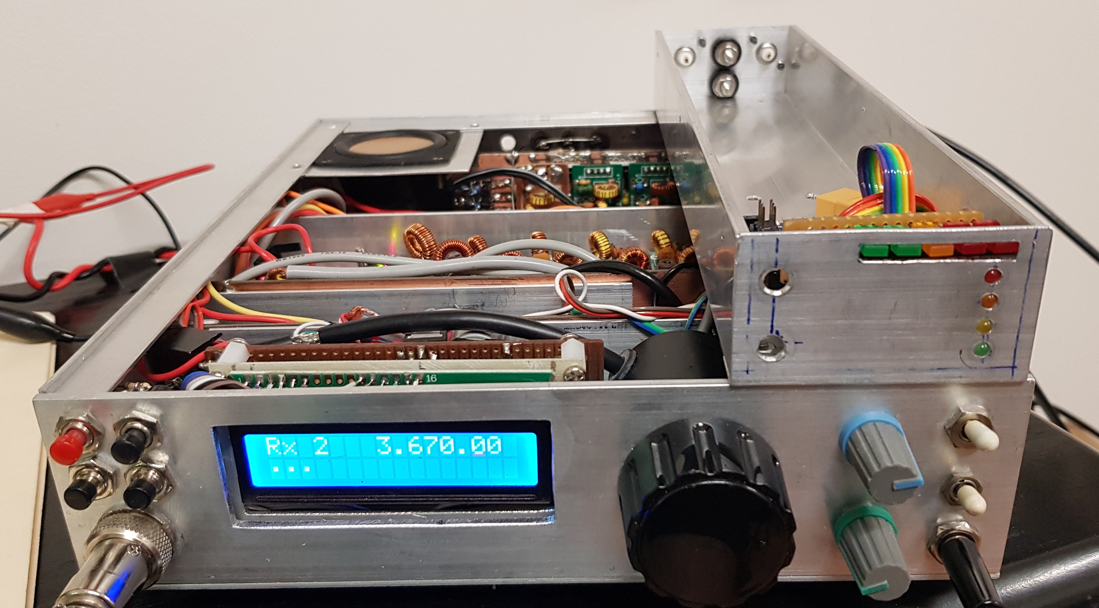 Aluminum U-channel chassis, made to pair with my homebrew transceiver (Summit Prowler IV).
 An advantage of aluminum channel doubling as the casing is that you can feel its heat. To add thermal mass, I added a rectangular piece of 10mm thick aluminium stock (more of a ‘block’ than a sheet) cut to fit under the FETs. Thus heat from the FETS warms the 10mm aluminium block, then convects to the channel. A small computer fan wired into the ‘operate’ side of the standby switch moves air over it all, ducting out through the hole cut in the side of the cannel for Nano USB access. In use, the case gets warm but not hot after 10 minutes of alternate overs in a typical SSB ragchew, and the little fan helps significantly to keep things thermally under control.
Current limiting
After blowing up some of his FETs, Andrew VK3JBL added in a current limiting circuit, based on the one by G0KLA in a similar push-pull amplifier (using IRF510s). G0KLA claims that this allowed his amplifier to survive transmitting into any SWR from an open circuit to a short. I decided to leave this out — if the amp proved to be unreliable as a result of driving odd impedances from hastily thrown up link dipoles or squid pole verticals with insufficient radials, it would be added later. So far, it’s not been necessary.
Sourcing
The only components I needed to explicitly order online were the IRFZ24N FETs and the ferrite block for the output transformer (element14). I ordered four FETs, two spares, in case I experienced a ‘power FET rifle shot’ any point. As mentioned, the 500 and 600v SMD LPF capacitors are from Minikits.
Arduino pin plan
Here’s how the Arduino is used. There’s plenty of scope to expand what the MCU is doing. Additional features could include sensing the heatsink temperature and turning on the fan (to implement a ‘thermostatic fan’); sensing the PTT or RF sense lines and using script logic to sequence the two relays; or monitoring current and implementing over-current protection. Another option in the future is to dispense with all the LEDs and use a 128×64 OLED on I2C.
D0: (Serial)
D1: (Serial)
D2: Bar meter LED 1
D3: Bar meter LED 2
D4: Bar meter LED 3
D5: Bar meter LED 4
D6: Bar meter LED 5
D7: Band relay & indicator LED (80m)
D8: Band relay & indicator LED (40m)
D9: Band relay & indicator LED (30m)
D10: Band relay & indicator LED (20/17m)
D11: NC
D12: NC
D13: NC
A0: RF sense (in)
A1: NC
A2: NC
A3: NC
A4: Reserved I2C SDA
A5: Reserved I2C SCL
A6: NC
A7: NC.
LPFs
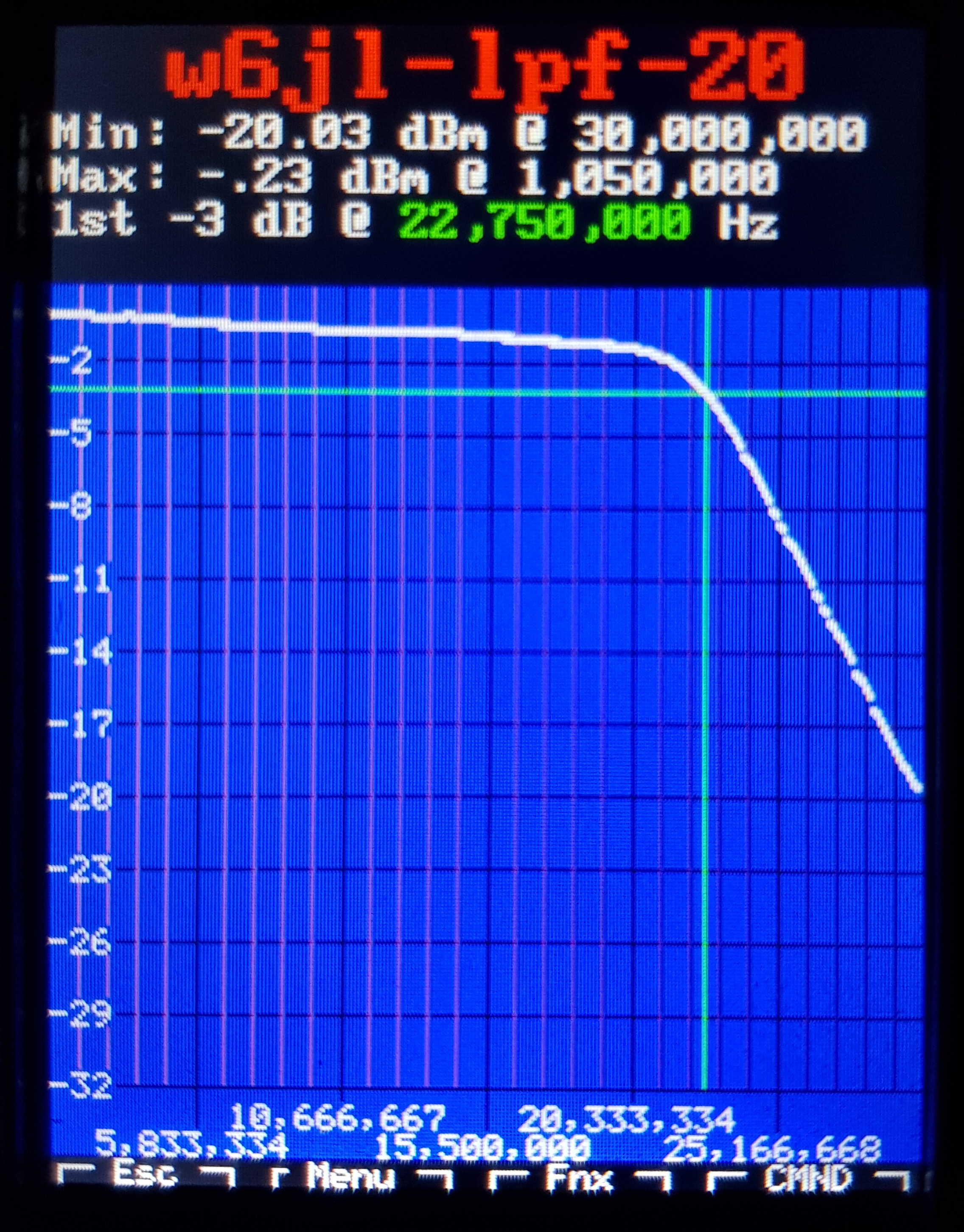
The LPFs were built from the W6JL article, reproducing Don’s design exactly for the 40, 30 and 20m filters. In the 80m filter, to make it fit in the limited space, a T68-2 was used instead of the recommended T82-2 toroid, adjusting the number of turns to match the inductance. The sweeps are shown. The 20m filter looks a little shallow but X-axis was left at 1-30MHz for all four filters, for consistency. I used new, good quality ceramic 500 and 600V 1208 SMD capacitors, from Minikits.


Performance
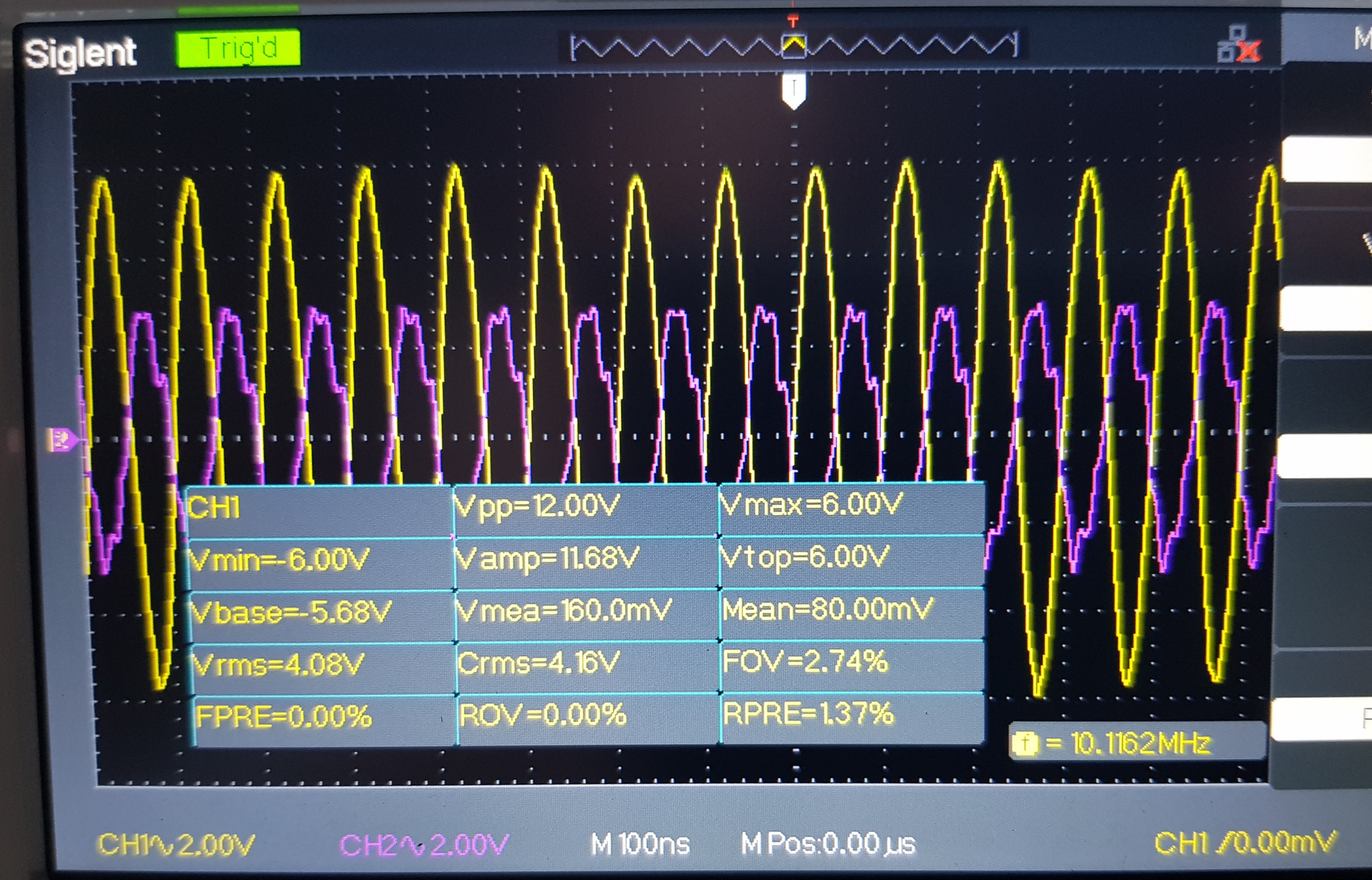
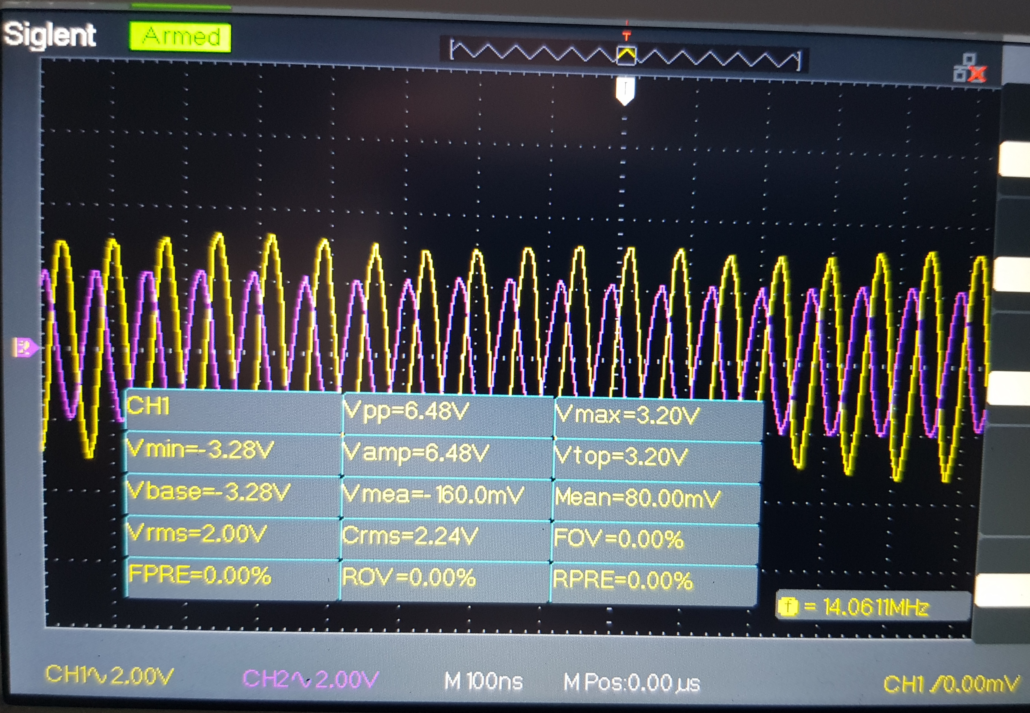
The following table presents measured power gain on the four bands. The effect of the 3dB input pad (switched automatically into the amplifier’s input circuit on 80 and 40 meters) is taken into account. Overall, the amp is delivering in the range 8 to 10dB from 80 to 30m inclusive.
| Band | Drive (Vpp) | Drive pwr (Watts) | Amp (Vpp) | Amp pwr (Watts) | Gain (dB) |
|---|---|---|---|---|---|
| 80 | 51 | 6 (3 ignoring pad) ) | 126 | 39 | 8.1 (11.1 ignoring pad) |
| 40 | 56 | 8 (4 ignoring pad) | 122 | 39 | 6.9 (9.9 ignoring pad) |
| 30 | 59 | 8 | 120 | 38 | 6.7 |
| 20 | 39 | 4 | 65 | 10 | 4.4 |
The lower output result on 20m may be partly due to the lower drive level (my transceiver drops off markedly on 20m). VK3JBL also got lower power on 20m (15W) when driven with an FT817 — he put this down to the provenance of his FETs. As my FETs are good quality product, sourced from element14, I think it’s a characteristic of the design, not the semiconductors. Glenn VK3PE tried the IRFZ34Ns and got more gain, his version of the amp delivered more than 50 watts with 0.5 to 1 watt drive. An option for the future.


Closing comments
The amp has been working well, and I have high hopes that it will prove to be reliable. An interesting thread on eHam compares it with the HFPacker 50 Watt amp, a more sophisticated design using four RD16HHF1 FETs, feedback, over-current protection among other features. My reading of the thread is that in its basic form, the W6JL amp will work reliably, as long as you a) keep the supply at or below 14V, b) don’t transmit into an open or short circuit, and c) don’t drive it with anything more than 5 watts. I won’t have any problem with c) or a) (as long as I keep it off my 20V LiPo packs). As far as b) is concerned, it’s possible that I’ll not set up the antenna properly sooner or later, and blow a three legged silicon fuse.
Overall, this was a good build experience, and I recommend the amp to anyone wanting around 50 watts of RF power on the lower to mid HF bands at 13.8 volts, without expensive, finicky FETs, or the need for elaborate cooling or construction techniques.

Great build Paul, looks really nice with the built in LPFs. I have only blown one set of FETS, that was about 3 years on when fiddling with the LPF. Mine is not very efficient = makes lots of heat too. Output on 4 cell LiFePO4 (~14V) is 55W post filter 40m and 45W on 20m. I only eeked out the last few watts in recent times.
LikeLike
Thanks Glenn. Your build was an inspiration for me to choose this option. The tiny fan directly over the FETs makes a big difference. Before I added it, mine got really hot too.
You are getting more power out than I am. One reason will be the 3dB pad I added on the input for 80 and 40m. The pad is out of circuit for 30 and 20, so doesnt explain the low output on 20. I think the lower drive on 20 must be answer as the amp draws less than 2 amps on that band.
Another thing I could try is to fiddle with the input transformer. Glenn VK3PE did this and improved the input matching significantly.
LikeLike
Great job Paul ..i also finished PA from Mike Kosor with 2x irf510 and i m very interesting for arduino control LPFs..73 de 9a3xz Mikele
LikeLiked by 1 person
Good work Mikele, in this amp I simply use a 2n7000 FET switch on each of 4 Arduino digital pins. The FETs switch the 2 relays either side of the LPF. Simple. In other projects I use I2C to talk to a PCF8574 decoder, with the same 2n7000 arrangement on each output pin. Good luck.
LikeLike
Thanks…now i waiting the book from ei9gq and talking with Glenn vk3pe and when i finishing the analog part of this transcivier, i m very interesting for your raduino with pcf8574 and for this 2n7000 switching but we will talking about for 2-3 mounths 😉 🙂
LikeLike
Good to see it finished Paul. I should pull mine out and re-do the performance numbers etc. Maybe use it on one of the QRP builds eventually.
I bought some high power 0.01 ohm shunts from Element 14. Lost the part number but a search for 0.01R should find it. They are a U shaped loop about 5c piece in size. No doubt the NANO could read the current and trip the power off if a fault condition.
Glenn
vk3pe
LikeLike
Thanks for your comments Glenn. I think this amp would be a good choice for a homebrew lower HF band transceiver. So far the FETs have held up. I used it on two summits on Mt Buffalo last week and, surprise, I got much better reports! In fact on The Hump I was apparently as strong as most of the chasers.
Thanks for the shunt tip, a DC current sensor is a good thing to have, I might get a few with my next order and try it out with a 12v halogen light globe.
73 Paul VK3HN.
LikeLike
Paul,I just want to say thank you for the information around the protective circuit G0KLA that helped me a lot. then my transistors works good ,now i wanna try with IRFZ34 .Thank you !
LikeLike
OK Mikele, yes the G0KLA amp and write-up is a good piece of work for sure, I studied it carefully when thinking about which amp to build. I like the W6JL amp because it delivers the power on a 13v rail, important when considering taking it portable. 73 and good luck with your IRFZ24 experiments.
By the way I’ve used it on three or more summits with success, and quite a lot at home, and so far, fingers crossed, it seems perfectly reliable. No smoke!
LikeLike
Yes….my english isnt good, but i mean for wa2eby amplifier,now i wanna also try finish w6jl amplifier also with g0kla stage.For portable qso s maybe is better W6jl amp. on 13V.
LikeLiked by 1 person
[…] of padding is a good choice of driver. There are many recent builds of this design, including by me and Glenn VK3PE. Don W6JL is a master homebrewer, if you haven’t seen his all-homebrew high […]
LikeLike
Result my experiment;
When i used irf510
1- power in 5w; pow. out 45w
When i used irfz24n;
Power in 5w; pow out 55w
2- when i used irf510 in 5 minute, system produced 65 degree celcius heat.
When i used irfz24n in 5 minute,
System produced 45 degree celcius heat.
Result: accurding to me:
Mystry is hidding under “high fidelity”
İrfz24n has more high fidelity than irfz510.
That is, irfz24n converting dc energy more RF energy.
irf510 converting dc energy less RF energy.
Mystry is HIGH FIDELITY.
LikeLike
Very interesting Dundar and it is good practice to try different things, test, and record your results as you have done. Then, based on looking at your data, you can propose a theory. In your case, that the IRFZ24N is more ‘hi fi’ than the IRF510!
I haven’t tried IRF510 in this circuit but I can imagine they should work. However did you run both tests on 13.8V? To get 45W out of a pair of IRG510s I think you would have to run them at 28V. The good thing about the IRFZ24N is they deliver 50 watts on a 13v supply.
Good luck! 73 Paul VK3HN.
LikeLike