
The FAT5 project is a 100 watt Class E AM transmitter from Dave GW4GTE and Eric GW8LJJ, dating back to 2011. The name derives from Dave’s desire to design a 100 watt AM workhorse using contemporary FETs to rival the ubiquitous AT5, a widely used war surplus boat anchor for low band AM.
The FAT5 project
The FAT5 project is a collection of modules and kits, including a DDS module for a VFO, the class E FET power amplifier (PA), variations on a linear modulator using stereo amplifier ICs (TDA2050, LM3886), a microphone amplifier with compressor and audio filtering, a sequencer to control receive/transmit switching, a simple AM receiver using a consumer grade AM radio IC, and the piece de resistance— a Pulse Width Modulator for the ultimate in power-efficient AM transmission. At a minimum, you could build a linear modulator and the PA, add a 24v 7A switch mode power supply brick and a generic microphone amp for a reliable 100 watt AM transmitter on 160, 80 or 40m.
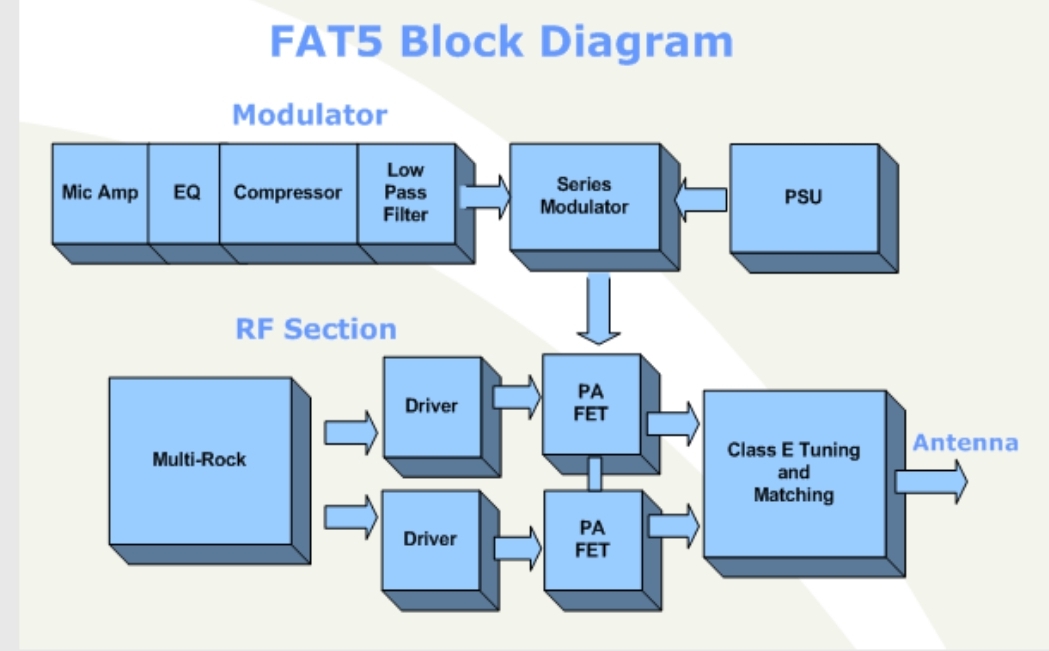
Several things attracted me to this design. The class E PA couldn’t be simpler, as is true for most of these designs. They are essentially a big push-pull switch clocked with anti phase square waves. Also, no modulation transformer — the linear modulator drives three parallel 2N3055 power transistors with the PA in the combined emitters, acting as the load in a 100 watt emitter follower. One more plus, the FETs doing the heavy lifting are IRF640s, which are both cheap and readily available.
I emailed Eric after seeing his many FAT5 builds on his qrz.com page. Eric patiently answered my questions, a great help when planning a build like this. I started on parts sourcing, planning to try the linear modulator before tackling the PWM. Parts started to accumulate in a cardboard box. A light steel 19 inch 2U rack chassis was earmarked. An excess 40v + 40v 300VA toroidal power transformer was gathering dust in another corner. Time to get cracking.
Circuit
The PDF of the complete circuit is here: FAT5_160_AM_Tx
Power supply
Eric uses a 24V 10A switch mode PSU with EMI filtering. I wanted this project to draw down the junk box as much as possible so I decided to make a variable voltage 10A regulated linear supply. No switching noise to worry about, but a lot of heat to disperse. I used the classic LM317 variable regulator feeding the bases of four 2N3055s as emitter followers, on two heat sinks– the same emitter follower pattern as used by Dave’s modulator output stage.
My 40v secondaries yielded 57 volts unloaded so I used the LM317HV variant which tolerates 60V. The PSU worked fine, but load tests with 40 and 50 watt halogen lamps made the 2N3055s alarmingly hot after only 30 seconds. To cool them, I mounted a 50x50mm 12V fan on each heatsink, directly over the transistors — this made a significant difference. AM is 100% duty cycle, plus the modulator power consumption, so the power supply is much bigger than I am used to.
I wound on two additional windings (44 turns each) that are rectified, filtered and regulated to 12 and 15V DC with 78-series regulators — one for the oscillator and audio boards, the other for the fans. Keeping the fans on a separate secondary was done for isolation from the sensitive audio input circuitry. The fan supply includes a bipolar switch that may be driven by an Arduino down the track — fans are noisy and are only needed when transmitting.

Oscillator (first attempt)
I planned to keep this transmitter simple, a crystal oscillator followed by a hex inverter to square and phase shift the output. I had crystals on 1825, 1843 and 1852 kHz. The 74HC04 buffer would be keyed for T/R switching.


I made the crystal oscillator module in an unconventional fashion, to fit snugly in a 50mm space underneath the rack boxes’ shelf. This way, the oscillator and all audio modules would be underneath, power supply and RF power stages above. I made a backboard with three 0.1″ sockets, each to hold a small double-sided card with a surface mount oscillator on each side, one for transmit, one for receive. The receiver crystal oscillators are a placeholder for a future AM receiver board. That project is left for another day.
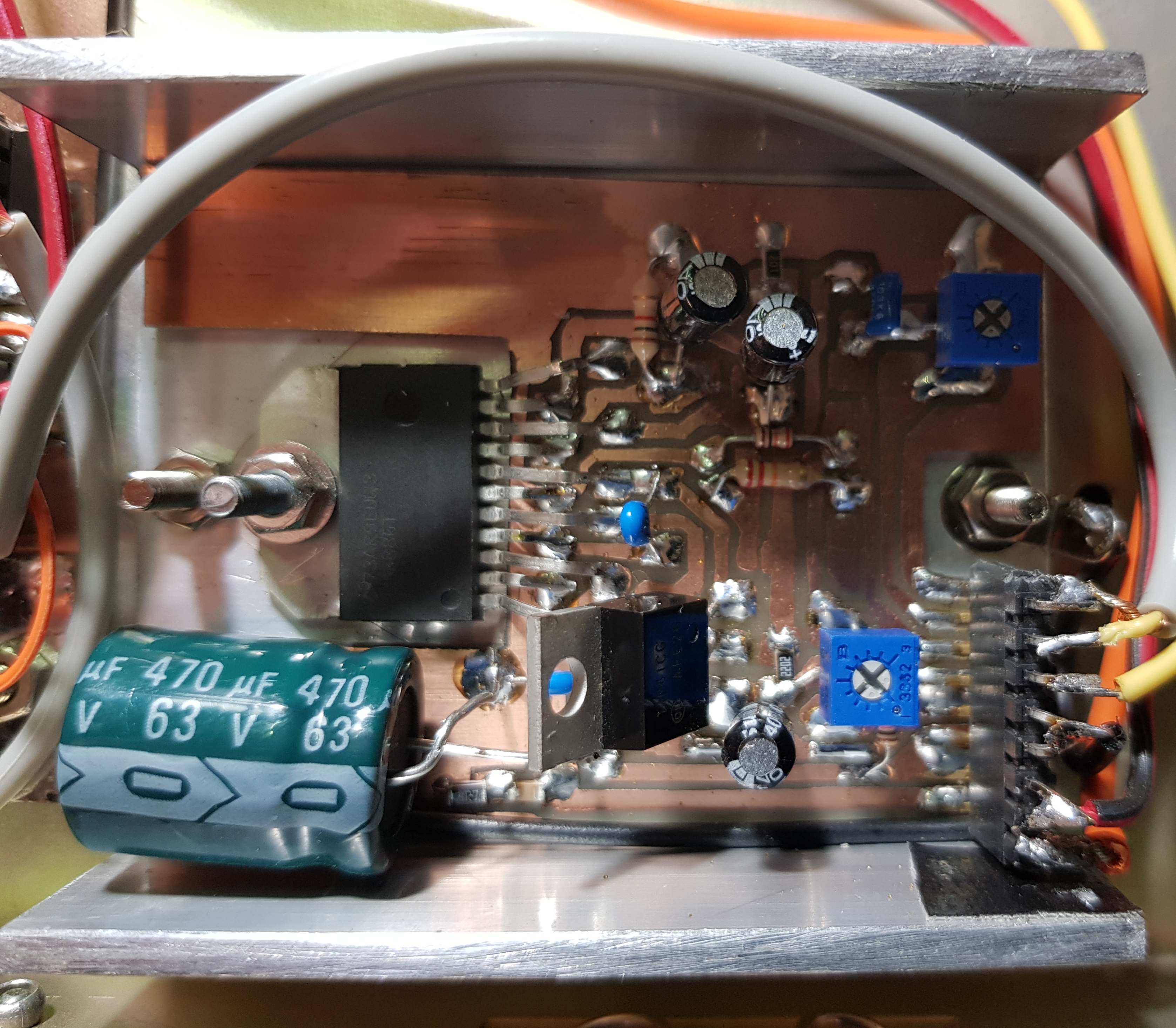
Modulator
I made up the FAT5 linear modulator using a LM3886 on a hand made board, designed to fit inside an aluminum U-channel for heat sinking. The IC uses +-25 volts, split from the 40 to 50v rail, to develop 50 watts. As noted, there is no modulation transformer, this audio power amp drives three parallel 2N3055s in a parallel emitter follower configuration, with the RF PA as the emitter load. The 2N3055s are mounted on a large heatsink under the chassis. Fan cooling was added to push air across the heatsink.
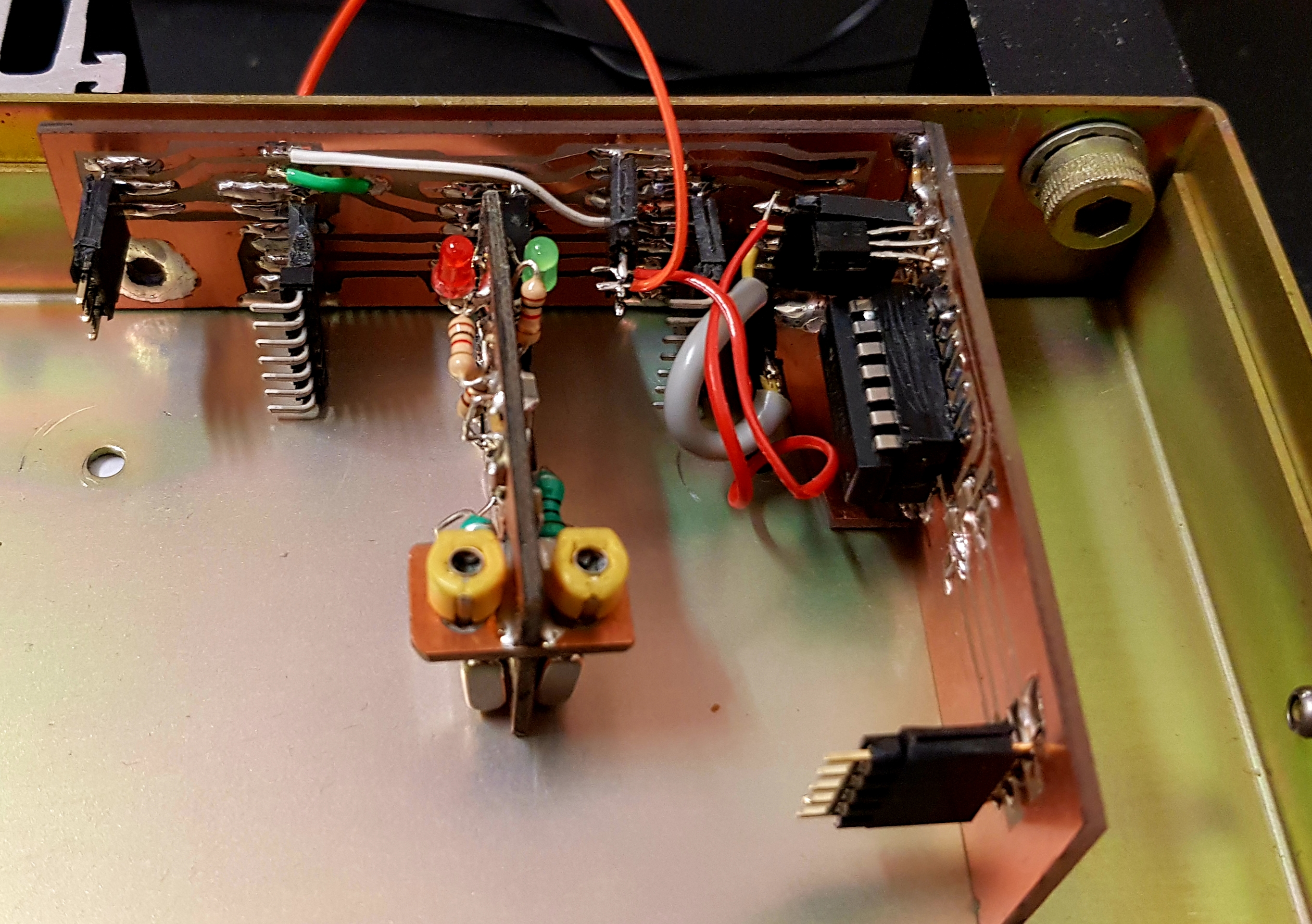
Mic amp/compressor
The FAT5 project includes a well thought out mic amp, compressor and limiter, all done with discrete ICs and components. I wanted to try an alternative approach that would avoid the build complexity, cost and time — a $3 SSM2167 module from eBay. These postage stamp sized units host the compander IC, set for 20dB audio gain, and the option to wire in potentiometers for compression and gain. I socketed one on a larger bespoke board with the pots, voltage regulator and connectors.

100 Watt RF PA
This module couldn’t be simpler. It is a symmetrical set of two IRF640 FETs on a heatsink and a TC4422 driver. I mounted this module on the top side of the chassis, shielded by a piece of aluminium angle.
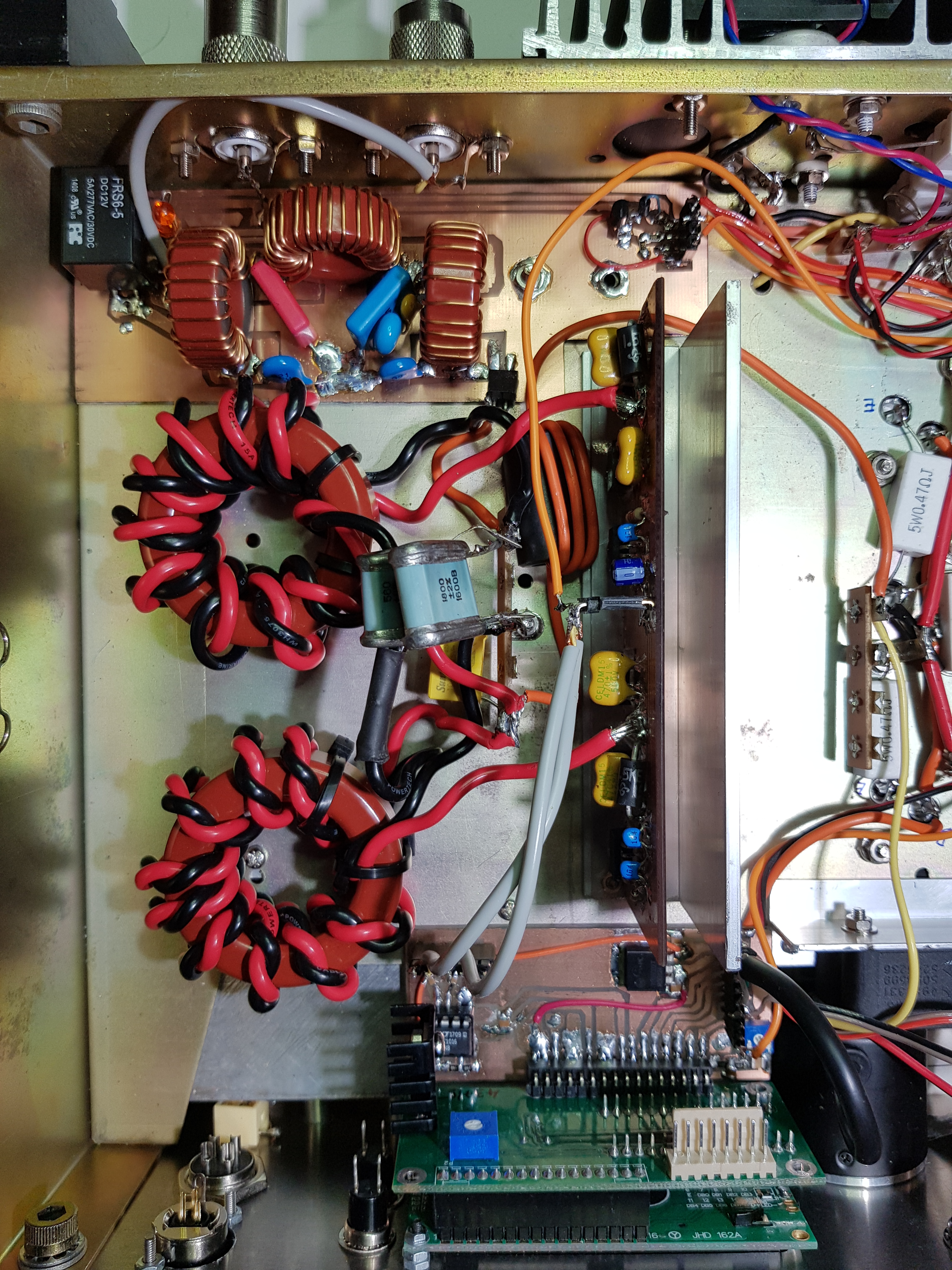
Matching
The FAT5 project offers two RF to antenna matching options. I chose the option with two T200-2 toroids wound with heavy insulated bifilar windings. A loading variable capacitor is called for to optimise the PA efficiency. For testing, I used a fixed 2nF 1.6kV silver mica capacitor.
LPF
The seven element LPF was made to the W3NQN design, with T106-2 toroids, probably significant overkill, as the W3NQN paper suggests T68-2 are suitable for 100 watts at 1.8MHz. But the bigger donuts were on hand. Suppression of the even harmonics is what counts with a push pull PA. The resulting filter shows around -50dB attenuation at the 3rd harmonic at 5.4MHz.


Antenna
Back in 2017 I made up a 160m inverted L for the 160m SOTA challenge. On that occasion I used a Drew Diamond VK3XU 30 watt AM/CW transmitter and receiver, story here. The antenna is made in light weight insulated multi-strand wire, not likely to last a long time in the weather, but good enough to get a signal out on top band.
The antenna is a basic inverted L, 1/4 wave (132′) driven element, and four 1/4 wave radials, lying on the ground. No fancy matching at the feed point. All the radials run in the same direction, along the length of my suburban block, lying directly under the driven element. The arrangement yielded an SWR of 1.9:1, close enough.
My ground is typical Eltham clay, from about December the grass is brown, and the ground rock hard. I have a well placed mature eucalypt, and the inverted L was thrown over it, reaching a height of about 15m (50′) before it bends thru 90 degrees for the horizontal section.

Initial testing and QSOs
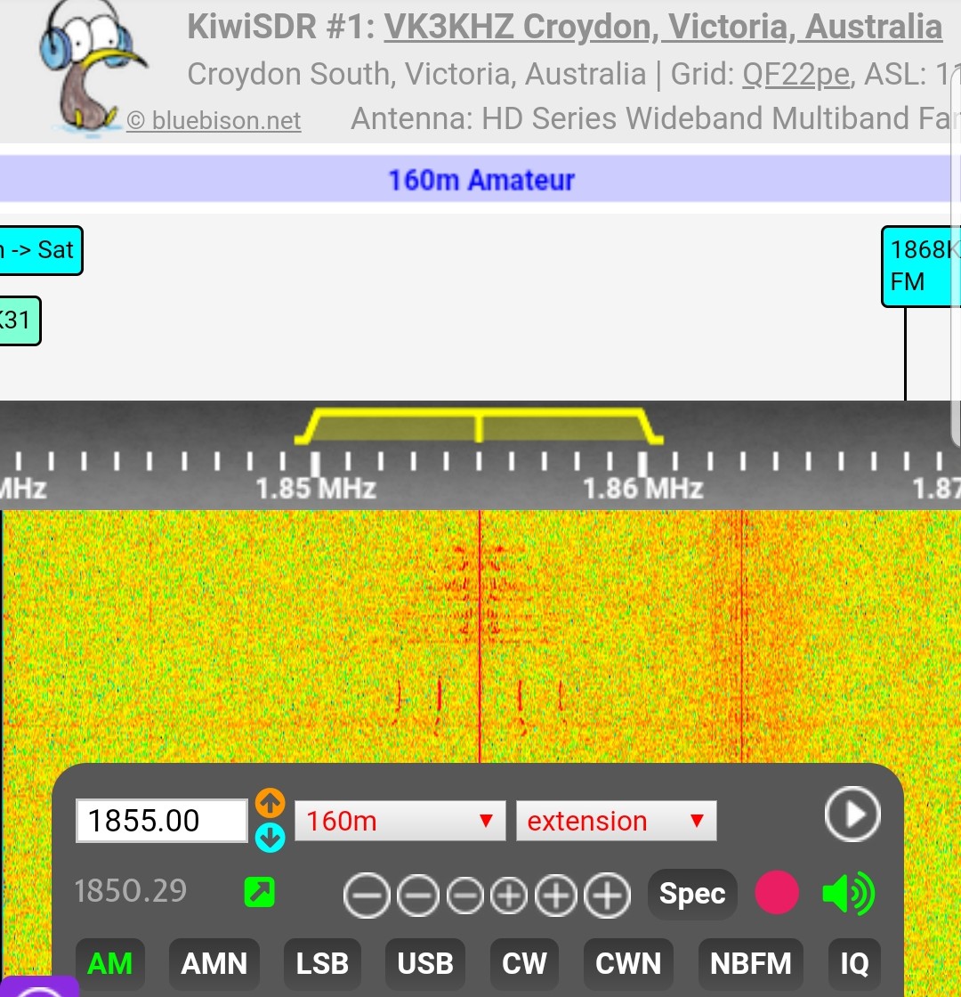
On air testing brought about a call from Peter VK3TKK across town. Signals were not strong and we both used the VK3KHZ SDR in the Melbourne suburb of Croydon South for reliable copy. The modulation level seemed a bit low and I found myself running the audio chain at full gain.
The next QSO was with Brendan VK3MH in nearby Briar Hill. Brendan was most helpful, reporting back on audio quality and bandwidth. It was during this QSO that I pushed the supply up to 50V, and the mic gain up higher, after which the 180V transient suppressor diode across the RF FET drains burned up, followed by a resistor in the power supply. Every failure is an opportunity to learn. I was about to learn about TVS devices.
Transient Suppressors
The transient suppressor devices used in this design and others are bidirectional voltage peak suppressors, in the form of back to back avalanche diodes. They are used in telecommunications to minimise transients on long lines, from induction, lightning, etc. Above their rated voltage they clamp and start to dissipate the excess power. In this application they protect the RF FETs from excessive waveform excursions. So if you overdrive a transmitter, or push the Vsupply, they conduct the peaks away, until such time as their dissipation capacity is exceeded, at which point they fail.
Transient Suppressors can fail in various ways. The ones in my transmitter short. That protects the RF FETs nicely, but shorts the Vsupply, which is, of course, protected with a fuse. Or in my case, not.
Fortunately no damage was done to my power supply, and after cleaning the burn marks off the PCB, replacing the transient suppressor and ventilating the shack, the transmitter was on air again. This whole smelly process was repeated a day later before I finally put in a 7.5A fuse.
At one point I ‘scoped the output of the crystal oscillators and was surprised at what I saw, a distorted waveform (from both cystals). This translated into an unbalanced digital waveform — the reason why one TVS was stressing. I fiddled with the crystal oscillators for a while before taking a break and having a bit of a think about things.
Oscillator (second attempt)
Eric suggested an alternative scheme, to run the VFO at signal frequency and use a high speed comparator IC, which delivers binary outputs (LT1016). His circuit, pure simplicity, is on this page.


Coffee Break Net
In Melbourne, the Coffee Break Net (1825kHz, Amplitude Modulation, 1100 local time, Mon-Fri) is legendary. It’s been running continuously for about 50 years. On the 3rd April 2019 I was able to check in for the first time. This group of gents represent an enormous collection of amateur radio wisdom and experience. Many are running homebrew AM transmitters and other gear. What they don’t know about homebrew 160m AM is not worth knowing.
Signal reports were mostly good and as expected. Several commented that the audio was too bassy. Bob VK3AIC made the suggestion to reduce the value of the coupling capacitor at the modulator input, down to something like 1n5. I replaced the 0.47uF with a 0.01 with the desired result.
I recorded and edited the group’s discussion of my signal, parts appear on the video.
Back on air
As well as getting the Raduino (si5351) PLL VFO done, I used the two weeks to finish the front panel. The 3mm aluminum panel got a rub with 800 grade wet and dry emery paper, a metal primer, and three coats of flat black enamel. Then DecaDry rub-on labels, then three coats of clear satin enamel with a very light run between sprays. This process takes a number of days but the end result is worth it — I’ve been making front panels exactly like this for 40 years!

With the near perfect anti phase drive clocks, the RF PA now ran as intended — cool, with an even increase in RF power with supply voltage.
On my notepad I noted that at 20v and 5A I was seeing 200Vpp (or 100W RF) as measured on the ‘scope. That’s 100% efficiency, so I suspected the analogue volt meter and ammeter were a bit out. At 25v and 6.5A on the RF PA I noted 250Vpp RF into the antenna, 150w RF.
Reconnecting the modulator which places half Vsupply on the FETs, I saw 35V at 6A, 210W DC input, including modulator, delivering 220Vpp out, 125W RF carrier. The end was in sight.
Reflection
A few thoughts about this build. Firstly, class E is remarkable in that it delivers medium to high power levels around 90% efficiency; the FET and driver devices are commonplace and cheap, and the circuitry runs warm at most. Another feature is that the power output is directly proportional to the supply voltage, not the drive level. Compared to conventional linear PAs, it almost seems too good to be true.
Thinking that crystal oscillators could be squared and then used to deliver acceptable anti-phase signals was perhaps optimistic. It might have worked after a good deal of fussing but I expect each crystal would have demanded its own treatment. Not reproducible or stable.
The variable voltage power supply was a real asset, allowing drive to be slowly increased from 12v to 50v. At about 25V the thing comes alive as the LM3886 turns on, putting half the Vsupply on the RF FETs. An ammeter in series with the power supply is essential for understanding what’s happening. On air monitoring via the VK3KHZ SDR confirmed that the transmitter was functional. Modulation maybe on the low side, but workable.
The biggest benefit from this project for me is that it has opened up access to the 160m AM community, a bunch of highly experienced experimenters and makers. Better still, they’re a friendly bunch, keen to welcome a newcomer with soldering iron in hand.

Components that released their smoke during this project.
What’s next?
There is a reasonable amount of CW activity at the bottom end of the 160m band, including DX. At the time of writing, VI9NI was active from Norfolk Island. My Arduino script has CW, all the controls, and a keyer with basic memories and semi breakin. A circuit will be required to replace the modulated HT with the full unmodulated HT. Or make the 2n3055s swing up to the full rail, which would avoid switching at high current HT line. A mod for a rainy day.
In terms of future 160m transmitter work, the FAT5 project has a nice Pulse Width Modulation (PWM) module which would dispense with the LM3886 stage and the large, hot 3 x 2N3055s. A smaller, lighter modulator suggests the option of a battery powered 40 to 50 watt transmitter for CW and AM portable work, SOTA, or just to have for those country drives.
Acknowledgments
Thanks to:
- Drew Diamond VK3XU for discussing aspects of class E AM over the past few years
- Eric GW8LJJ for email support during this build
- VK3 160m Coffee Break Net regulars for the reports (VK3s XU, AIC, ARY, DQ, ZPQ, AX, HK, CKL, CSJ, SJ, sure I’ve missed others)
- everyone I’ve met on 160m AM in recent weeks.
Materials and sourcing
Most of the semiconductors are from RS Components and Rockby.
The 300VA 40 plus 40V toroidal transformer is discontinued stock from Jaycar. Altronics still has a good range. You can pick up mid-sized toroidal mains transformers from hamfests and surplus outlets, and secondaries are easily wound on. Most AM transmitter builders use ex telecom or server switch mode supplies, too good and cheap to ignore.
Meters, enameled copper wire for additional secondaries, various easy to find components from Jaycar.
Replacement front panel is 3mm aluminum, cut in the shop to 482mm x 88mm. Action Aluminium, Thomastown, $15 for two pieces.
Class E resources
Class E Radio site.
AM Fone site, class E forum.

fantastic build Paul, looks really nice.
LikeLike
Tnx Glenn. Have been doing more homebrewing than activating, obviously.
LikeLike
That’s an impressive amount of building! I don’t know where you find the time…
You really should try your hand at PCB CAD and SMT devices – I bet you could halve the size of the box!
LikeLike
Time is the currency of our age. Spend it wisely!
I,’m all SMD now, apart from QRO projects like this. You probably cannot see it, but the drivers for the TR relay and the fans are mostly SM.
As for PCB CAD, one day, hand drawn boards are still working fine for me.
73 David, thanks for commenting, de VK3HN.
LikeLike
excellent job ,bravooo,i still not finished my ei9gq rtx 😉 😉 😉
LikeLike
Thanks Mikele, it’s good to finish projects to the stage where you can make a video or a blog post. But the journey is more important than the finish line!
LikeLike
Great job, Paul. Good to see the NAT SNA has come in handy for you. The rack case looks like an obsolete Philips base station rack, judging by the handles.
Glenn
vk3pe
LikeLike
Yes thanks to you Glenn I am using the SNA to sweep filters and antennas. The rack box is indeed old Philips gear, hamfest catch, with replacement front panel in aluminum. It was some kind of switch. Good box, easy to repurpose. I like the handles, a nice industrial design touch.
LikeLike
Hello, this might be off topic, but where did you get the html template for this website? Thanks.
LikeLike
It’s wordpress.
LikeLike
Awesome AM rig Paul! I saw your post on AM fone and said that’s Paul – I didn’t know he was an AM guy. Of course the last time we corresponded about Arduino’s and home brew SSB/CW rigs I wasn’t an AM guy either.
I made my first (after 48 years in the hobby) AM QSO just a few months ago using a Globe Chief CW rig with a MOSFET based HB modulator in series with the 807 cathodes. AC0OB mentored me on vacuum tubes and shared details of his cathode modulation approach.
Anyway, I’m having a blast with AM and my 15 watt carrier is doing a decent job but I really want to get to the 100W or higher level. I really like the approach you have taken here and may have to give it a try myself. Look for some e-mails from me.
LikeLike
Gday Jerry,
Thanks for popping up on my blog again. So my secret is out, I’m not an exclusive QRP guy. Under that meek exterior lies a brawny QROer, building 00 watt AM transmitters and dreaming about bigger ones still! Good to see that our interests converge once again.
I have always liked AM, and we have a good 160 ‘culture’ here in VK, with SSB and AM activity every night and one of the longest running AM nets probably anywhere in the world (the Coffee Break Net, 11am, 1825, it’s been running since the 1960s).
I recently met several VK3s who have been designing and homebrewing Class D and E AM transmitters and they piqued my interest. Class E PAs are amazing, you can build a 90% efficient 100 watt PA with a dozen parts or less. Building the FAT5 160m AM Class E transmitter was lots of fun, and a different project to those QRP SSB rigs. One thing I’ve noticed is that I’m buying all sorts of new parts, like big toroids and FETs and ICs I never knew existed. Also, you need a good dummy load!
The Class E Forum on AMFone is a goldmine and the Town Square of the Class E gang. Hang out there, study their designs, and you’ll have a lot of options. I didn’t discover it until after building the FAT5 design (which by the way is a fine option). Incidentally I modified my Arduino/si5351 script to generate signal frequency and key CLK#1 on PTT. A version is on github, ask me for the latest versions before you try to use it.
Good luck with your AM build. Paul VK3HN.
LikeLike
Very Good AM Transmitter Paul ,
LikeLike
Thanks Hendro. I’ve subsequently replaced the linear modulator with a pulse width modulator. Much mire efficient! 73.
LikeLiked by 1 person
[…] driven with my FAT5 160 AM transmitter, which delivers almost exactly 50 watts of un-modulated carrier, it gets hot after about 2 minutes, […]
LikeLike
[…] complement two 160m AM transmitter projects I built in 2019 (one finished, one on the workbench) I wanted to build an AM-only receiver. No BFO, no product detector, just a […]
LikeLike
[…] BlogVK3HN Youtube ChannelVK3HN SI5351 LibraryVK3HN FAT5 AM TransmitterVK3HN Linear ModulatorVK3HN AM […]
LikeLike