
After a few months of operating my FAT5 160m AM Class E transmitter with its linear modulator, it was time to try Dave and Eric’s Pulse Width Modular module (PuWMa). This is a PWM using the Texas Instruments’ UCC25701 PWM chip, with TC4421 drivers and IRF640 switching FETs, followed by the obligatory Low Pass Filter to clean the 170kHz AC off the modulated DC.
PWM
I won’t attempt to explain Pulse Width Modulation, there are lots of people far more knowledgeable to do that, and plenty of good videos and other explanations. Just a few impressions. In essence, all pulse width modulation schemes, be they for dimming a LED, controlling the speed of a motor or modulating an RF carrier, work by varying the mark space ratio (duty cycle) in a pulse train, which varies the waveform’s power. The controlled power is then converted into a form that can power a load (lamp, motor, RF PA).
When used to dim a LED, the high frequency component causes the LED to flicker on and off at a high frequency that the eye cannot normally detect in the emitted light (in most cases), so the pulse duration circuitry can directly drive the LED load without issue. In a motor controller, the motor’s inductance rejects the high frequency energy.
But when used in a series modulated AM transmitter the baseband energy in the modulated waveform needs to be conveyed to the load, and the higher frequency energy stripped off. That’s done by a low pass filter, designed exactly in the fashion of RF LPFs we homebrewers are familiar with, except that the cutoff frequency is supersonic rather than (high) radio frequency, and the inductors are in series with the power supply to the PA so they must be capable of handling the RF power amplifier’s maximum DC input current.
The effect of the LPF can easily be seen by scoping around the LPF board. Scoping the output of the PuWMa PWM (the drains of the IRF640 switching FETs) reveals the modulated 172kHz pulse train swinging almost the complete supply rail, due to the very high efficiency of FETs as switches. Moving the scope to the LPF output reveals steady state DC representing the average power present in the wave. If the mark space ratio is 50% the DC will be Vss/2 less a small amount for the fairly minimal losses. Applying modulation (speaking into the microphone) varies the on/off ratio of the waveform which translates into variations in the DC voltage at the LPF output. Voila. Modulated HT. This is what directly powers the RF PA stage.
Overall, pulse width modulators are remarkably efficient, in terms of the ratio of input power they consume to output power delivered into the load, around mid 90 percent efficient. This means very little energy is wasted as heat. So high efficiency (cool running), no modulation transformer, and small size make PWM the ideal companion to a similarly efficient Class D or E RF PA in an AM transmitter.
Construction
Normally I make my own PCBs but in this case, the circuit was nontrivial and the PWM chip reportedly works only within a narrow DC supply rail and may be fussy in other ways, so I ordered a board from Eric GW8LJJ which came soon enough. The only thing requiring any planning was the heatsink bracket to ensure it would fit into the shallow space underneath the chassis floor in my transmitter’s 19″ rack box.
As discussed above, the LPF is where the pulse train fundamental and all of the switching hash is stripped off, allowing only the modulated DC to pass. The PuWMA design dictated T200-26 toroids. I had trouble finding a convenient source. The ham suppliers don’t carry them as they are sub-HF. In fact the only users I expect would be hobbyist makers of higher power switch-mode gear. Of which there cannot be many.
A scan around the Class E Forum revealed that LPF inductors are being wound on a wide variety of cores and formers, including ferrite pot cores (such as RM10), toroids, and air. I did manage to find some T106-26 donuts from Rockby, half the size but not small, and at least made of the right material.
After consulting Eric GW8LJJ about my options I decided to try them. Since toroids.info doesn’t support them, I looked further and found a calculator for them. Interestingly, the number of turns for the inductance called for, 88 and 36uH, was almost identical for both T200 and T106 sizes.

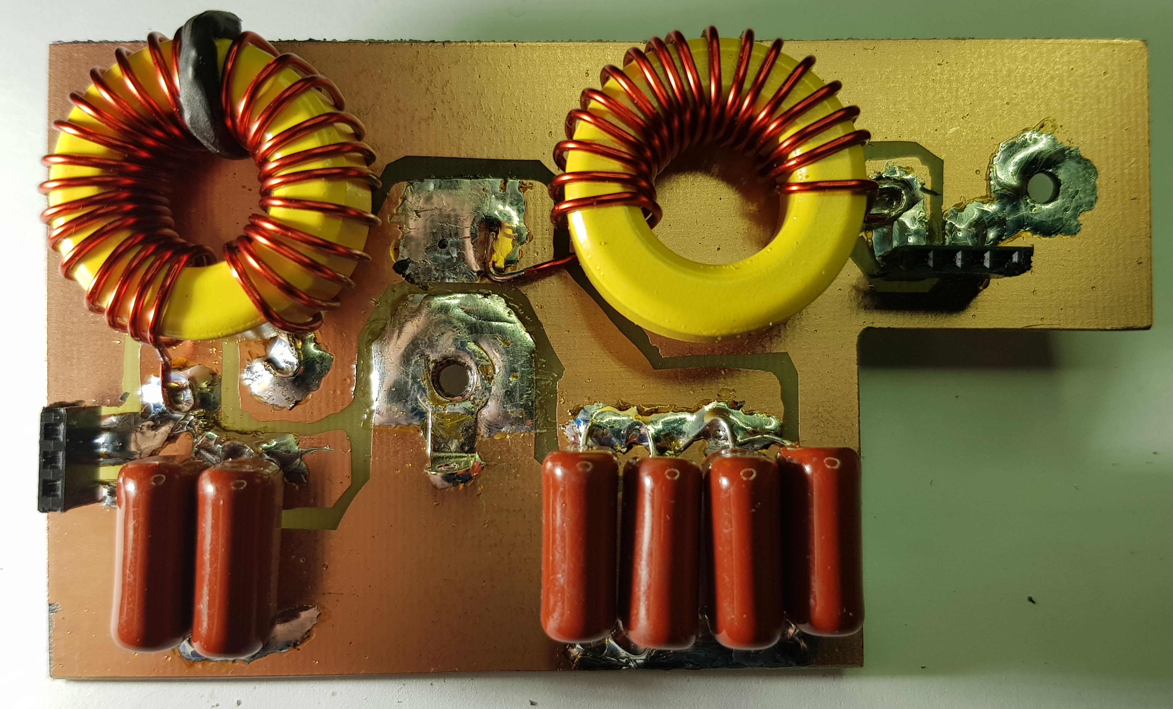
FAT5 pulse width modulator on the GW8LJJ PCB.
PWM experimenters require dummy loads, not only for their transmitters, but also for the PWM itself. I soldered eight 47 ohm 10 watt resistors in parallel. In the photo below, it’s nicely warm after 10 minutes with only 13.8v on the PWM FET drains.

Testing
After making sure the DC supply was set to 13.8v, the PWM board worked first time, generating a 172kHz square wave, shown below at the gates of the switching FETs. The mark space ratio was set roughly using the hand and eye method.

At the LPF output I measured half the DC supply. I connected up an electret microphone via an external audio preamp to get line level output, which I connected to the input of the PWM. My best whistle (639Hz by chance) modulated to high levels (the photo shows 73% modulation but it was going much further than that).

Noise
Winding up the AC scope channel to look at the un-modulated DC output, residual 300mV pulses were visible. A decent DC choke in the HT line should clean this up.


As a modulator
Building the PWM into my 160m AM transmitter was straightforward as I had designed the PWM heatsink/bracket and bespoke LPF board to snugly fit some spare space underneath. A couple of mods were required, however.
First, the 12v DC supply for the mic preamp and Arduino/si5351 needed to be increased to 13.8v. Fortunately I had anticipated this back last summer during the power supply construction by using a 7815 regulator (instead of a 7812), followed by a string of 1A diodes to bring it down to below 13v. Shorting out two of these diodes brought the voltage under load to 13.6v. Perfect. The 7805 regulator on the Arduino board got a little hot, I will keep an eye (I mean finger) on it.
Second, the PUWMA module includes active high and active low enable inputs for T/R switching. Some basic sequencing was needed. When going from standby to transmit, the sequence is:
1. Mute receiver
2. Energise the T/R relay
3. Turn the VFO on (at the transmit frequency)
4. Apply drive (enable PWM).
And the reverse when reverting from transmit to standby.
Having an Arduino controller makes this kind of thing simple. My script was already sequencing the T/R relay and VFO. A spare digital pin (D6), already brought out to a header and unused, was adopted as the PWM enable line, active high. Code was added to enable /disable it with short delays, and wrapped in #defines to ensure those few lines of code are only compiled for this project.
A thought. We don’t want the PWM to be enabled, even for a fraction of a second, at power up or Arduino reset. Arduino digital pins are tri-state and are set to float at power-up, allowing an external resistor to pull them high or low. A 10k to deck was added.
Testing
With the new modulator mounted and wired in, and with the transmitter variable HT supply set to 20v, bench tests into a PWM dummy load were conducted. All looked OK.
After dummy load tests and monitoring it was time to get on air. The LPF output was connected to the RF PA. Immediate success. Everything cool. Current draw considerably less than with the previous linear modulator. Checked PA FET gate and drain waveforms, although to be honest, not really sure what level of ragged-ness is unacceptable.
On air and monitoring on the VK3KHZ SDR across town, I had good sounding modulation, albeit low. Lots of experimentation followed, trying more microphone preamp gain, an external audio compressor limiter I’ve had for years, different duty cycles, all at different power levels. This was not without incident.
Smoke
First I blew and replaced the LM317HV in the regulator. Next, a much bigger failure that ended a 4 or 5 minute test transmission, one of the FETs in the PWM and a second one in the RF blew. At this stage I began to doubt the IRF640s in the PA. In discussion, Wayne suggested replacing them with the higher rated IRF840.
There’s no current or SWR sensing in this transmitter, so if anything goes astray, the only protection is a 7.5A fuse. A more sophisticated power supply regulator would include these features and may have avoided this and several other burnouts.
On another alignment matter, Eric had told me, but it didn’t sink in at first, that setting the PWM duty cycle to 40/60 allows the modulator to boost the positive swing to 100% to account for losses. This setting gave more modulation.
On air
Carefully setting the PWM duty cycle and the preamp and modulator audio gain controls with judicious local and cross-town remote monitoring gave me confidence in the signal. Brendan VK3MH in nearby Briar Hill recorded my 160m AM signal and sent me the video via Facebook. Further on air reports over a weekend confirmed the AM signal was of good quality, modulation depth and frequency range.
Acknowledgement
Ths project, my first pulse width modulator, taught me a lot about this technique. There’s so much more to learn. Thanks to Eric GW8LJJ, Wayne VK3ALK and Laurie VK3SJ for supporting emails and a few phone calls.
Pulse Width Modulation is to AM as Arduino and si5351 is to the VFO. Once the combination is tried, there’s no going back to their analog predecessors.

congrats Paul….very big and nice job ..excelent building !
LikeLike
Thanks Mikele. The digital scope makes all the difference, and it’s fun to use!! I’m watching your work too!
LikeLike
[…] variable power supply and connected it to a 6 ohm 80 watt dummy load I had used to test an earlier Pulse Width Modulator. The choke sang a high pitched whistle faintly as it delivered 90 watts into the […]
LikeLike