
The bottom ends of 80, 40 and 20m are not what they used to be. For starters, the busiest part is the digital segment where computers talk to computers – listening to this segment is like eavesdropping on a bunch of dialup bulletin boards having a party in 1983. Then there’s the CW segment. When there are CW signals to listen to, all are frequency stable, chirp and click-free, generated by more computers from deep inside rigs that are more computer than radio. These shining examples of digital CW perfection have traded efficiency and quality… for personality.
In 1979 as a teenager I spent countless hours scanning these frequencies on my FT200, and the sounds from those days are indelibly printed on my memory. The CW segments were a managerie of good, average and bad sounding fists, warbles and tones. There were the regular VK DX men with polished 599 emissions, frequency stable and chirp free, some with curious hand-keyed idioms and flourishes. There were JAs by the dozen, banging out formulaic patterned QSOs, and Eastern Europeans, some on their creaky old ex-WW2 equipment that had to be heard to be believed — sloppy, chirpy, drifty, and gloriously messy CW. And of course the Americans with their kilowatt CW reaching out half way around the globe, some with the self-assurance of a military comms man, armed and dangerous.
It was possible back then to tell where a station was from before hearing the callsign by the combination of signal quality and the operator’s fist. The key to this ability was variety. The CW segment was a rich technical and cultural melting pot of sounds and styles, like the marketplace in some kind of global village populated only by fanatical radio enthusiasts, the ham equivalent of the bar scene from Star Wars 4. In those days, sending a CW CQ gave me butterflies–you could be answered by absolutely anyone, or anything!
The loss of analogue CW struck me again when reading the comments under Peter VK3YE’s video on a two transistor CW transmitter, in which he tries different values of the VXO to PA coupling capacitor. 1nF gives ample drive but pulls the oscillator when keyed. 470pF gives lower drive but less chirp. The CW sound was evocative. Several viewers commented that they would always answer a chirpy CQ because it was likely to be a boat anchor or homebrew rig, something more exotic, perhaps something to discuss during the QSO. The thought of a chirpy CW signal being irresistible to some, a feeble flickering flame to which the morse moths are helplessly drawn, began to form.
Using digital technologies to simulate analogue predecessors for continuity or nostalgia is not unusual. Society has recognised the impact of the digital transition on those of us who are living through it. Melbourne Trams sound a digital facsimile of a 1920s bell, a sound synonymous with the city’s central shopping district for 120 years. Electric vehicles include computer controlled devices to generate a petrol engine’s sound to alert pedestrians, or in the case of the new Dodge, maintain faith with the rusted on fan base.
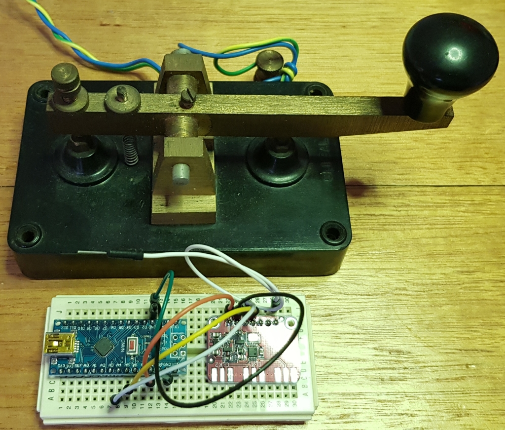
So, why not do the same for CW? It occurred to me that the power of microcontrollers and multisynth PLL clock generators could easily make this happen. It was a simple coding task to modify my keyer code to make small frequency shifts during dot and dash formation for chitp, and to consistently increment or decrement the oscillator’s base frequency to simulate drift. Time constants were #defined as labels for tuning. With a bit of experimenting, a reasonable approximation of both chirp and drift was found.

These first simulation attempts may be overly simple, as a typical analogue oscillator’s chirp does dot pull the frequency as a linear function of time, but rather, might pull hard, then ease off as the oscillator and subsequent amplifier stages settle down. The corresponding mathematical function is probably a complex polynomial. The same with drift. Most of my analogue oscillators have drifted in one direction, then reached some kind of equilibrium, thereby stabilizing. I’m not a big boat anchor guy, but I wouldn’t mind betting that certain old transmitters have their own chirp and drift signature. How else would you recognize them when you hear them?

I leave more sophisticated simulations of bad CW as an exercise for the reader. Same for the many ways you could use this CW party trick. For example, why not arrange for a switch that disengages the chirp and drift. You could call a chirpy CQ to attract attention, then when you snare someone, turn it off for computer-perfect CW. The options are endless.
If you are brave enough to use this, I ask only three simple things: use digichirp mode sparingly, don’t drift out of the band or segment, and don’t blame me for your bad signal quality reports!
Chirp gallery
Here’s a rogue’s gallery of dubious CW signals. Enjoy!

… well said, well presented, almost philosophical !
LikeLike
Thanks, there’s a little bit of philosophy in most things we do, you’ve just got to dig it out.
LikeLike
I love this project, seeding it for the first time in the recent SPRAT. It has been on my list of projects that would be nice to do, but now I found a nice implementation here.
73
LA3ZA
LikeLike
Hi Sverre, thanks for commenting, I am impressed that you appear to have thought about digital simulation of chirp and drift with an si5351. I hope you try my code, experiment a bit, and have fun! Paul VK3HN.
LikeLike
Love your description of the bands ‘ in the day’. Very evocative…
And the idea of recreating the chirp and drift is cool too!
VK2STG
LikeLike
Thanks for commenting Steven. 73!
LikeLike